Bumper assembly having progressive rate spring

a bumper assembly and progressive technology, applied in the direction of fluid removal, wellbore/well accessories, earth-moving drilling and mining, etc., can solve the problems of increasing the damage of affecting the production of oil and gas wells, and causing a lot of so as to reduce the damage, less damage, and less damage to the plunger and/or the bumper assembly

Inactive Publication Date: 2016-01-21
PATRIOT ARTIFICIAL ELEVATOR
View PDF13 Cites 5 Cited by
  • Summary
  • Abstract
  • Description
  • Claims
  • Application Information

AI Technical Summary

Benefits of technology

[0020]Use of a progressive rate spring in a bumper assembly better dampens the force imparted by a plunger to a bumper assembly than the use of a constant rate spring. For example, due to the outside diameter and length limitations mentioned above, a prior art constant rate spring used in a bumper assembly is designed to withstand impacts not exceeding 333 lbs / in. With the described length limitations, such a spring is limited to 3 inches of travel, thus limiting a constant rate spring to approximately 1,000 pounds of resistive force. A progressive rate spring, on the other hand, can have a 1,000 lbs / in rating, thereby providing three times the resistive force of a conventional constant rate spring.
[0021]This increase in dampening afforded by a progressive rate spring results in less damage to the plunger and / or bumper assembly caused by the free-fall impact delivered by a plunger to the bumper assembly, and because there is less damage to either component, neither one needs to be replaced or repaired as often, thereby saving time, money, and effectively increasing the productivity of the well.

Problems solved by technology

It is well known that production from oil and gas wells can suffer due to the build-up of fluids at the bottom of the well.
A number of problems have arisen from the use of prior art plungers.
Impacts between the plunger and the bottom of the well can be violent, and they often are so violent that damage occurs (either immediately or over time due to repeated use) to either the plunger and / or whatever it strikes at the bottom of the well.
Such damage can consist of deformation to the plunger and / or the fish neck, or even partial or total destruction of either one or both.
While the damage may not occur on the first impact (although it could), the repetitive nature of the operation of these devices often ultimately results in substantial damage to the plunger and / or bumper.
Replacing damaged plungers and / or bumper assemblies is both costly and time consuming.
Moreover, the time it takes to replace either, and especially a bumper assembly, entails “downtime” for the well, which itself imparts undesirable cost and expense.
Prior art assemblies such as that shown in FIG. 1 have not been totally effective.
For the most part, their ineffectiveness stems from their use in new shale plays.
The bypass plungers used today are heavier and fall at much higher velocities.
In other words, while such designs work to some extent, they do not work well enough because damage (as a result of their normal operation) still often results to the plunger and / or the bumper assembly.
Belleville washers have been used, as opposed to simply using a longer constant rate compression spring (which would absorb more force than a shorter constant rate compression spring), because the limited space afforded by standard lubricators at the top of the well (for inserting the bumper assembly into the top of the well) limits the length a spring can contribute to the overall length of the bumper assembly.
Similarly, using larger diameter springs (of the same length), which would absorb more force than an otherwise similar spring having a smaller diameter, are impractical because the standard width of drilling pipe acts as a barrier to using larger diameter springs.
With the described length limitations, such a spring is limited to 3 inches of travel, thus limiting a constant rate spring to approximately 1,000 pounds of resistive force.

Method used


Image

  • Bumper assembly having progressive rate spring
  • Bumper assembly having progressive rate spring
  • Bumper assembly having progressive rate spring

Examples


Embodiment Construction

[0027]The following description of the exemplary embodiments refers to the accompanying drawings. The same reference numbers in different drawings identify the same or similar elements. The following detailed description does not limit the invention. Instead, the scope of the invention is defined by the appended claims.

[0028]Reference throughout the specification to “one embodiment” or “an embodiment” means that a particular feature, structure or characteristic described in connection with an embodiment is included in at least one embodiment of the subject matter disclosed. Thus, the appearance of the phrases “in one embodiment” or “in an embodiment” (or variants thereof) in various places throughout the specification is not necessarily referring to the same embodiment. Further, the particular features, structures, or characteristics may be combined in any suitable manner in one or more embodiment. The invention, however, is not limited to any one embodiment.

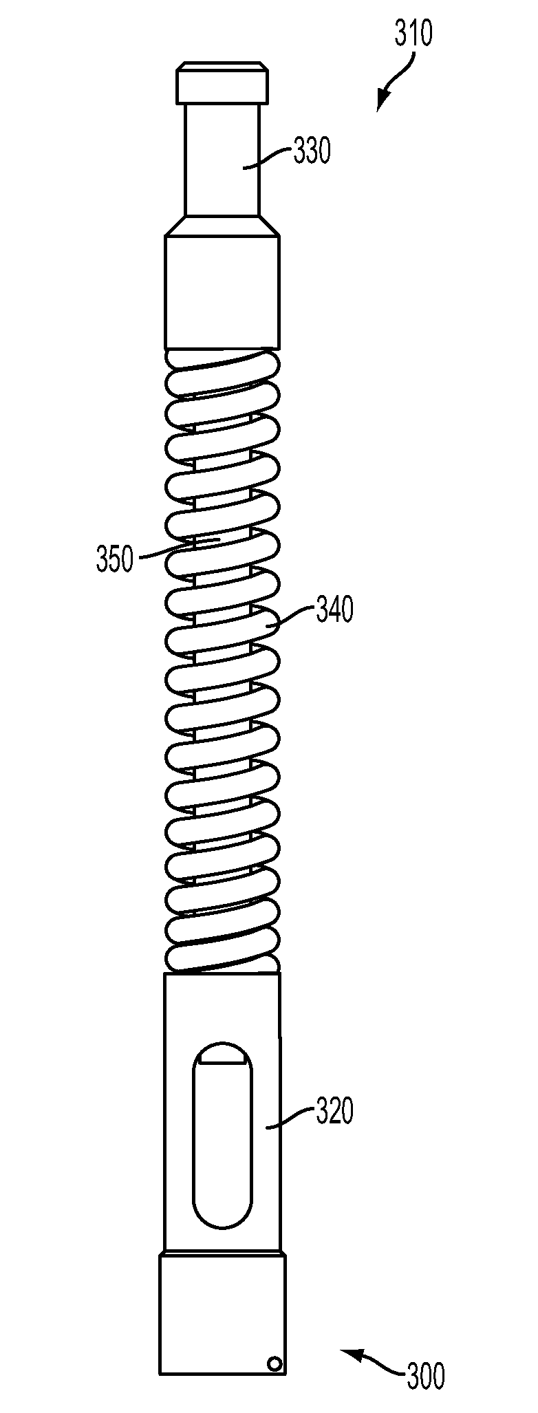
[0029]FIG. 3 illustrates...


PUM


Abstract

A bumper assembly for down-hole use in a well. In one embodiment, the bumper assembly includes a fish neck, a cage, and a progressive rate spring disposed there-between. When a plunger strikes the top of the fish neck, the progressive rate spring dampens the force delivered by the plunger, thereby prolonging the useful life of the plunger and/or the bumper assembly.

Description

BACKGROUND[0001]1. Technical Field[0002]Embodiments of the subject matter disclosed herein generally relate to methods and systems for stopping a plunger at or near the bottom of a well and reducing the impact damage caused thereby. In this regard, one embodiment of the present invention is directed to a bumper assembly that employs a progressive rate spring, which operates by dampening the force delivered (on impact) by the plunger to the top of the bumper assembly, thereby reducing the damage that would otherwise be caused by the impact, and prolonging the life of the plunger and bumper assembly as a result.[0003]2. Discussion of the Background[0004]It is well known that production from oil and gas wells can suffer due to the build-up of fluids at the bottom of the well. See e.g., U.S. Pat. No. 6,148,923, which is incorporated herein by reference. Various methods and devices have been developed to remove those fluids so as to improve the well's productivity.[0005]One such device i...

Claims


Application Information

Patent Timeline
Patent Type & Authority Applications(United States)
IPC IPC(8): E21B43/12
CPCE21B43/121E21B23/08
Inventor ROYCROFT, ROBERT G.MITCHUM, DARRELL W.
Owner PATRIOT ARTIFICIAL ELEVATOR
Why Eureka
Try Eureka