
Article Storage Facility and Method of Operating Same

a technology of storage facilities and articles, applied in the direction of storage devices, electromagnetic transmission optical aspects, loading/unloading, etc., can solve the problems of difficult for light signals to reach pickers that may exist on the track above or below the particular level, malfunction or perform, and certain constraints placed on the structure of the facility, so as to reduce interference

Active Publication Date: 2016-01-21
DAIFUKU CO LTD
View PDF7 Cites 8 Cited by
  • Summary
  • Abstract
  • Description
  • Claims
  • Application Information

AI Technical Summary

Benefits of technology

The present invention relates to a technology for reducing interference between light signals during optical communication in article storage facilities. The main technology involves performing temporally-divided light-emission control to enable only one first optical communication device to emit light in any one time period among multiple devices located close to each other in the vertical direction. This arrangement allows for reliable optical communication between devices and reduces interference between light signals, regardless of the structure of the article storage facility. Additionally, the invention suggests dividing the support shelves into groups and controlling emissions from first optical communication devices in each group to minimize interference and maintain operating efficiency of the article transport devices.

Problems solved by technology

For example, when light signals are transmitted from a plurality of first optical communication units in the same period, the light signals may interfere with one another, making it possible for the picker that received the light signals through the second optical communication unit to malfunction or perform a wrong operation.
The light signal transmitted from the first optical communication unit of a particular level is blocked by the tracks on the level above and below that particular level, making it difficult for the light signal to reach a picker that may exist on the track above or below the particular level.
However, since the first optical communication units are installed on the tracks, there is a certain constraint placed on the structure of the facility.

Method used


Image

  • Article Storage Facility and Method of Operating Same
  • Article Storage Facility and Method of Operating Same
  • Article Storage Facility and Method of Operating Same

Examples


Embodiment Construction

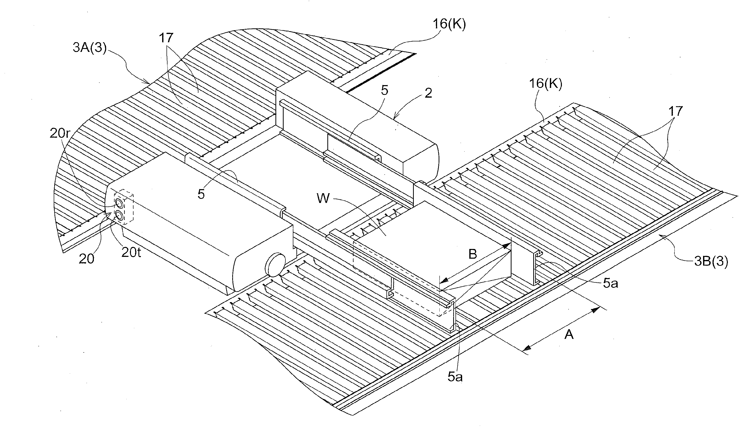
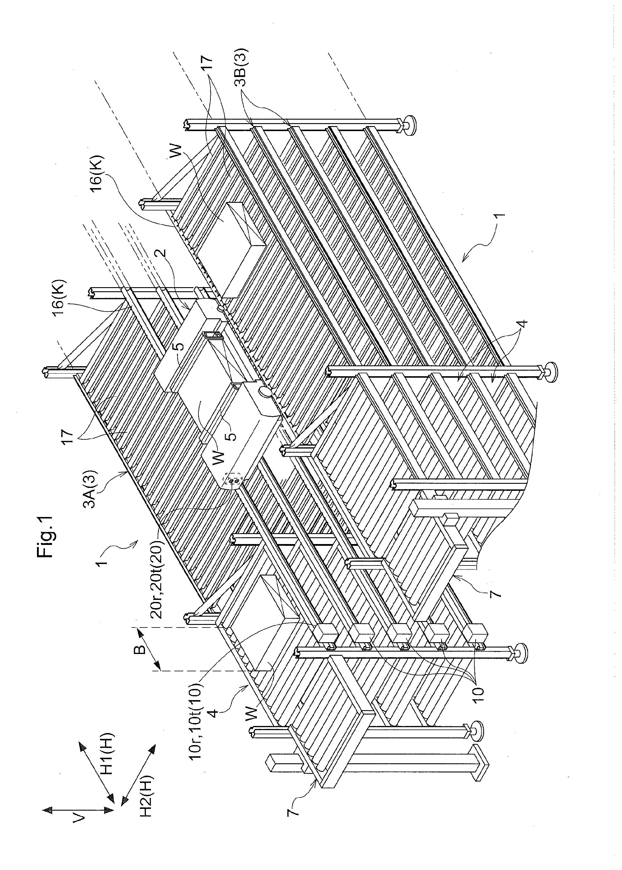
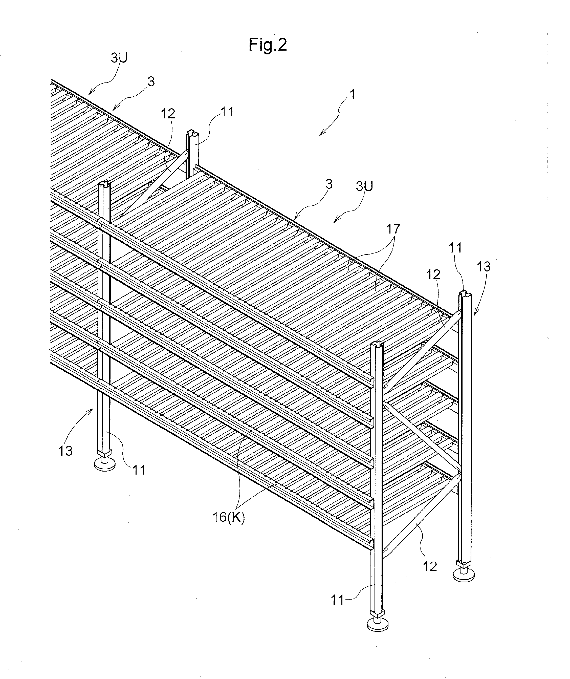
[0029]The embodiments of the present invention are described next with reference to the drawings. In the present embodiment, as shown in FIG. 1, an article storage facility includes article storage racks 1 each of which includes a plurality of levels of support shelves 3 spaced apart from one another in the vertical direction V, with each support shelf capable of storing a plurality of articles W arranged in a row (i.e., with any one article W located next to another) in a horizontal direction (a first horizontal direction H1 which is a horizontal direction and is a direction along which the articles are spaced apart from each other, or a longitudinal direction along which each support shelf 3 extends, as described below). In addition, the article storage facility is provided with travel paths K each of which extends along the longitudinal direction in which the support shelf 3 extends. In other words, the travel paths K extend along the first horizontal direction H1 which is the sa...


PUM


Abstract

A main controller controls carry in operations and carry out operations of articles to or from an article storage rack using article transport devices by causing a control command to be transmitted from a first optical communication device that is associated with each article transport device to a second optical communication device provided to each article transport device. The main controller is configured to perform a temporally-divided light-emission control in which a plurality of the first optical communication devices are caused to emit light in a temporally divided manner such that there is only one first optical communication device that emits light in any one time period among the first optical communication devices that are located close to one another in the vertical direction.

Description

CROSS-REFERENCE TO RELATED APPLICATION[0001]This application claims priority to Japanese Patent Application No. 2014-146996 filed Jul. 17, 2014, the disclosure of which is hereby incorporated in its entirety by reference.FIELD OF THE INVENTION[0002]The present invention relates to an article storage facility that performs carry in operations and carry out operations of articles using article transport devices as well as a method of operating such an article storage facility.BACKGROUND[0003]Article storage facilities, in which articles (which may be article containers for storing or holding articles) can be automatically carried in (i.e., stored) and carried out (i.e., retrieved), are widely in use. Such article storage facilities often have a plurality of levels of article storage shelves, that are spaced apart from one another, each of which can store a plurality of articles in the horizontal direction. As for how the articles are carried into and out of such an article storage fac...

Claims


Application Information

Patent Timeline
IPC IPC(8): B65G1/137B65G1/06
CPCB65G1/065B65G1/137B65G2203/044H04B10/80B65G1/0492
Inventor KOIDE, HIROYUKIYAMAZAKI, YASUHIRO
Owner DAIFUKU CO LTD
Learn More