
Unit for actuating lens, camera module, and optical apparatus

a technology for actuating lenses and optical equipment, applied in the direction of camera focusing arrangement, printers, instruments, etc., can solve the problems of short circuit between a terminal portion of the circuit board and an external electrical power, and so as to reduce the drop of magnets from the housing and enhance the operation reliability of the lens actuating unit.

Active Publication Date: 2016-01-14
LG INNOTEK CO LTD
View PDF7 Cites 30 Cited by
  • Summary
  • Abstract
  • Description
  • Claims
  • Application Information

AI Technical Summary

Benefits of technology

The present patent aims to improve the reliability of lens actuating units used in cameras. The technical effects of the patent include minimizing assembly tolerance of the magnets, securely fixing the magnet to the housing, and reducing the drop out of magnets from the housing. Additionally, the terminal portion of the circuit board, cover member, and base can be improved to increase the operation reliability of the lens actuating unit.

Problems solved by technology

However, the conventional lens actuating unit has a problem in that the magnets may be dropped out from the housing.
However, the conventional lens actuating unit has a problem in that the short circuit between a terminal portion of the circuit board and an external electrical power may occur.

Method used


Image

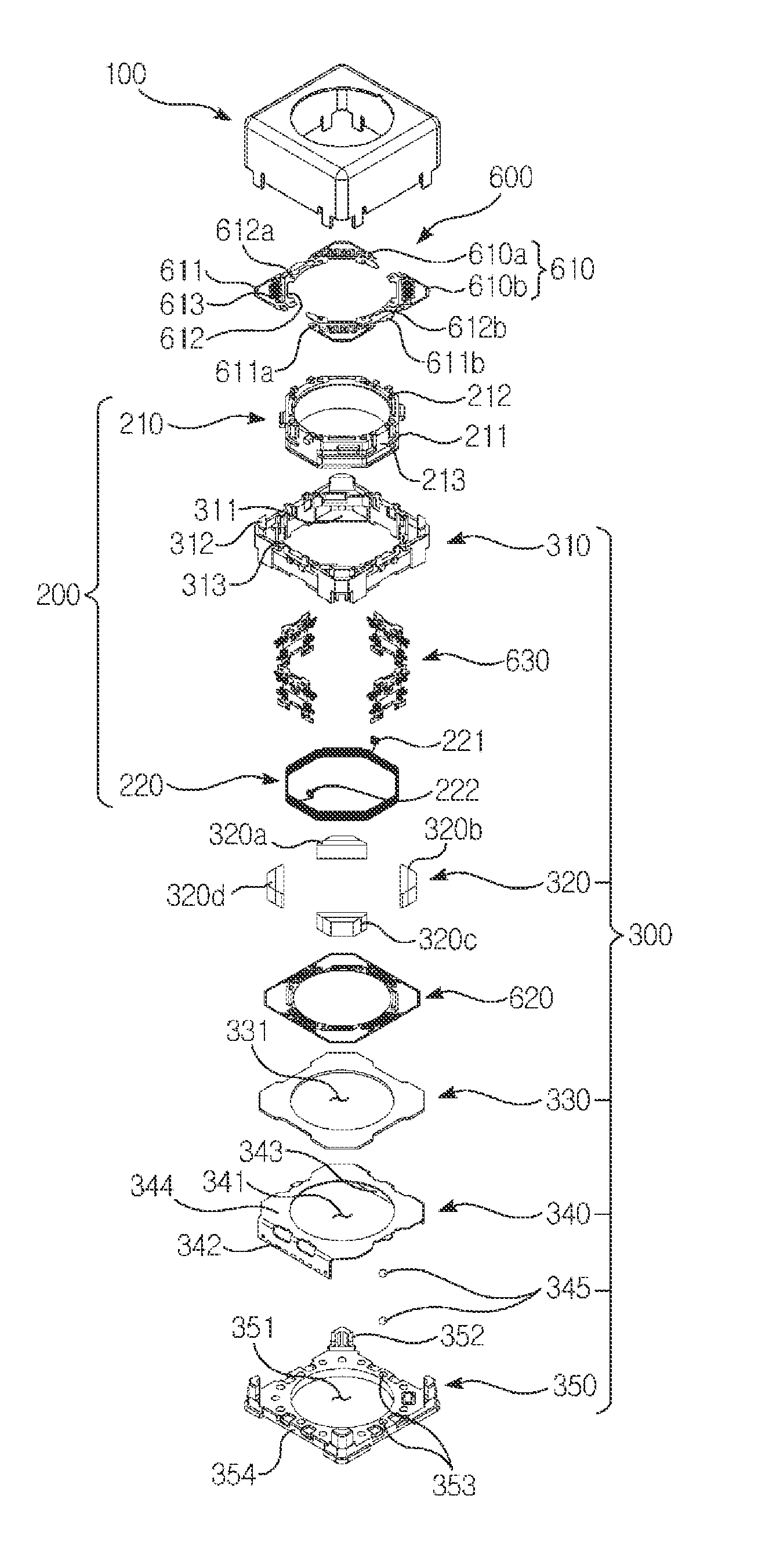
  • Unit for actuating lens, camera module, and optical apparatus
  • Unit for actuating lens, camera module, and optical apparatus
  • Unit for actuating lens, camera module, and optical apparatus

Examples


Embodiment Construction

[0069]Unless defined otherwise herein, all technical and scientific terms used herein have the same meaning as commonly understood by one of ordinary skill in the art to which this invention belongs. In a case when a term used herein conflicts with the customary meaning of the corresponding term, the meaning of the term defined herein shall supersede the customary meaning.

[0070]However, the terms mentioned herein are used merely for description of a particular exemplary embodiment. Thus, they are not intended to limit the scope of the present disclosure. Therefore, the definition of the terms shall be made based on the overall contents of the present disclosure. The same reference numbers are used throughout the present disclosure to refer to the identical elements of an exemplary embodiment.

[0071]Hereinafter, an optical apparatus according to an exemplary embodiment of the present disclosure will be described.

[0072]An optical apparatus according to an exemplary embodiment of the pr...


PUM


Abstract

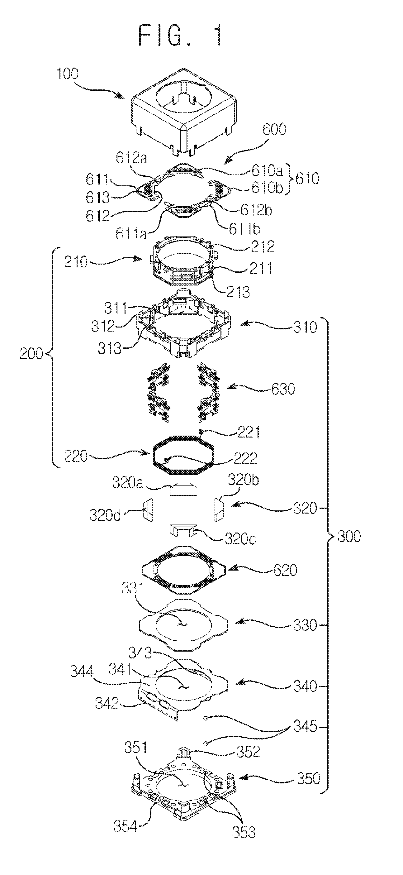
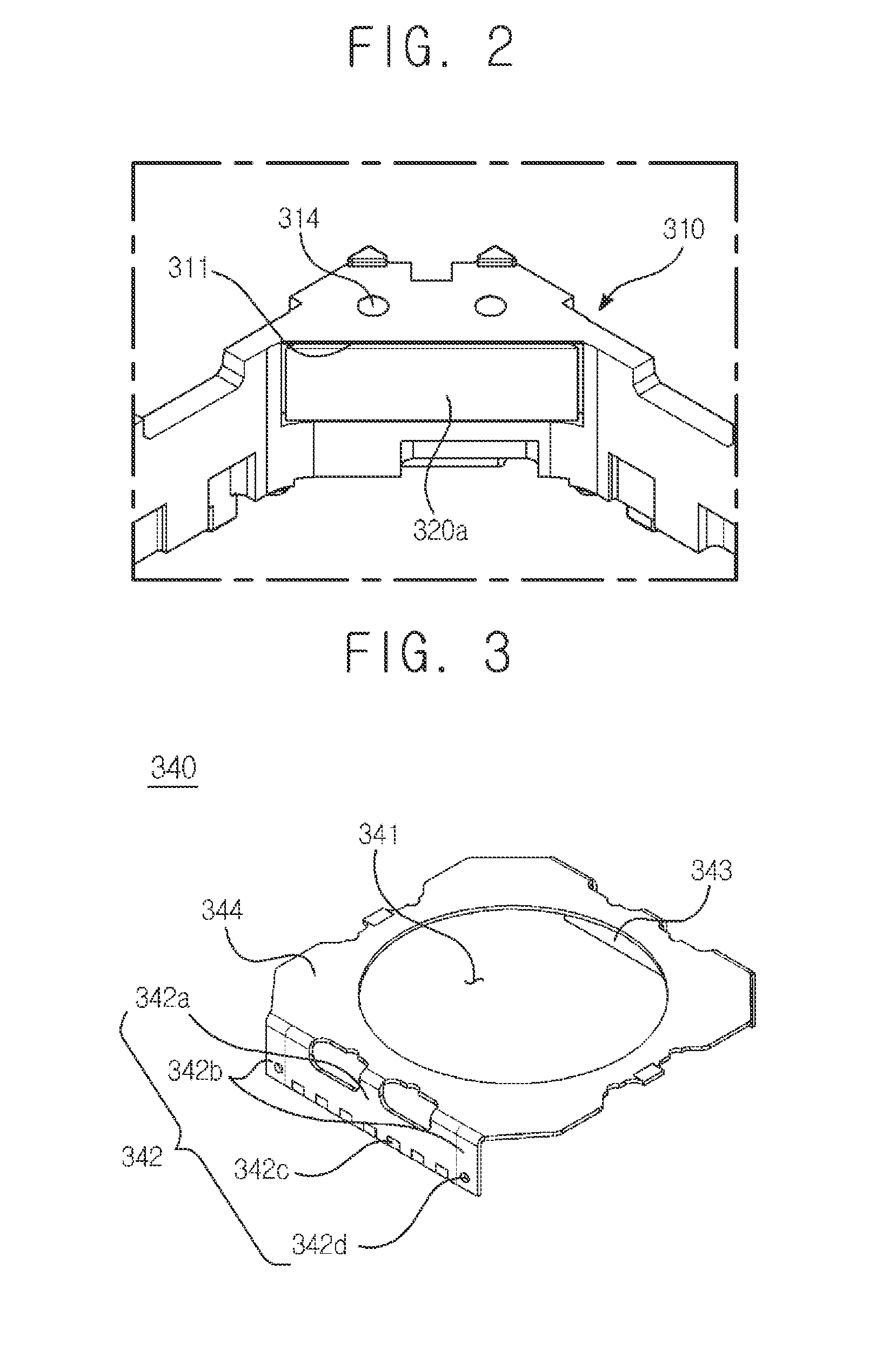
A lens actuating unit is provided. The lens actuating unit includes: a bobbin configured to accommodate a lens module at an inner side of the bobbin; a first coil unit disposed at the bobbin; a housing disposed at an outer side of the bobbin; and a magnet unit configured to move the first coil unit through electromagnetic interaction with the first coil unit, wherein the housing includes a hole formed by being recessed from an inner side to an outer side to accommodate the magnet unit.

Description

CROSS-REFERENCE TO RELATED APPLICATIONS[0001]This application claims the benefit under 35 U.S.C. §119 of Korean Application Nos. 10-2014-0087206, filed on Jul. 11, 2014; 10-2014-0087208, filed on Jul. 11, 2014; and 10-2014-0103557, filed on Aug. 11, 2014, which are hereby incorporated by reference in its entirety.BACKGROUND[0002]1. Field of the Invention[0003]The present disclosure relates to a lens actuating unit, a camera module and an optical apparatus.[0004]2. Background of the Related Art[0005]Concomitant with wide propagation of various mobile terminals and commercialization of wireless Internet services, demands by consumers related to the mobile terminals are diversified, and various types of additional equipment are attached to the mobile terminals.[0006]Among the various types of additional equipment, a camera module may be a representative device capable of editing and transmitting a still image or a moving picture, as necessary, by photographing the still image or the mo...

Claims


Application Information

Patent Timeline
Patent Type & Authority Applications(United States)
IPC IPC(8): G02B7/09G02B7/02G02B13/00G02B27/64G03B3/10
CPCG02B7/09G02B7/025G02B13/001G03B3/10G02B27/646
Inventor CHO, JAE HONGLEE, SANG HEEYEO, IN JAEHAN, JIN SUK
Owner LG INNOTEK CO LTD
Learn More