
Apparatus and method for estimating location, electronic apparatus comprising the apparatus

a technology of electronic equipment and location, applied in the direction of electrical equipment, instruments, measurement devices, etc., can solve the problems of difficult to receive signals from a plurality of base stations inside, four aps are required, and expensive to provide aps, etc., to achieve more precise position information

Inactive Publication Date: 2016-01-14
ELECTRONICS & TELECOMM RES INST
View PDF9 Cites 15 Cited by
  • Summary
  • Abstract
  • Description
  • Claims
  • Application Information

AI Technical Summary

Benefits of technology

The present invention provides an apparatus and method for accurately estimating the location of an electronic device without the need for additional equipment. This may be done by using information such as speed and direction of the device to correct the estimated position information. Overall, this technology allows for more precise location tracking of electronic devices.

Problems solved by technology

In the case of the wireless AP method, it is expensive to provide APs and an electric wave map needs to be built according to various indoor electric wave environments while an installation location of the AP needs to be adjusted.
Specifically, the wireless AP method has a problem in that at least four APs are required to perform indoor positioning.
In the case of the base station method, an intensity of a reception signal at each base station for a transmission signal of a terminal is measured to find a location through the electric wave map, resulting in a large positional error (200 to 300 m) and in many cases, it is difficult to receive signals from a plurality of base stations inside.
According to the method which uses a sensor, precision of provided position information is accurate outside but a GPS signal cannot be received inside so that an error is increased in accordance with the divergence of the sensor and a reference point inside needs to be noticed.

Method used


Image

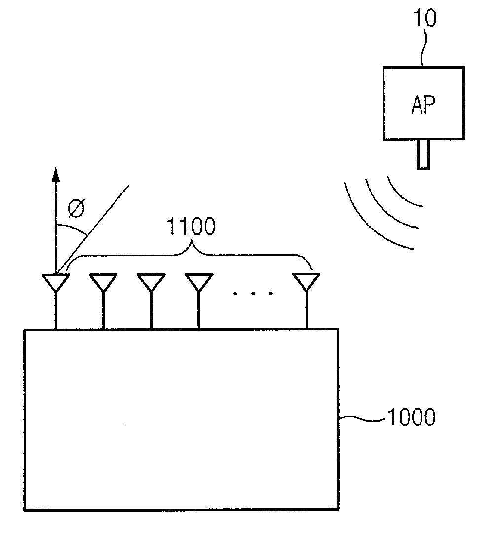
  • Apparatus and method for estimating location, electronic apparatus comprising the apparatus
  • Apparatus and method for estimating location, electronic apparatus comprising the apparatus
  • Apparatus and method for estimating location, electronic apparatus comprising the apparatus

Examples


Embodiment Construction

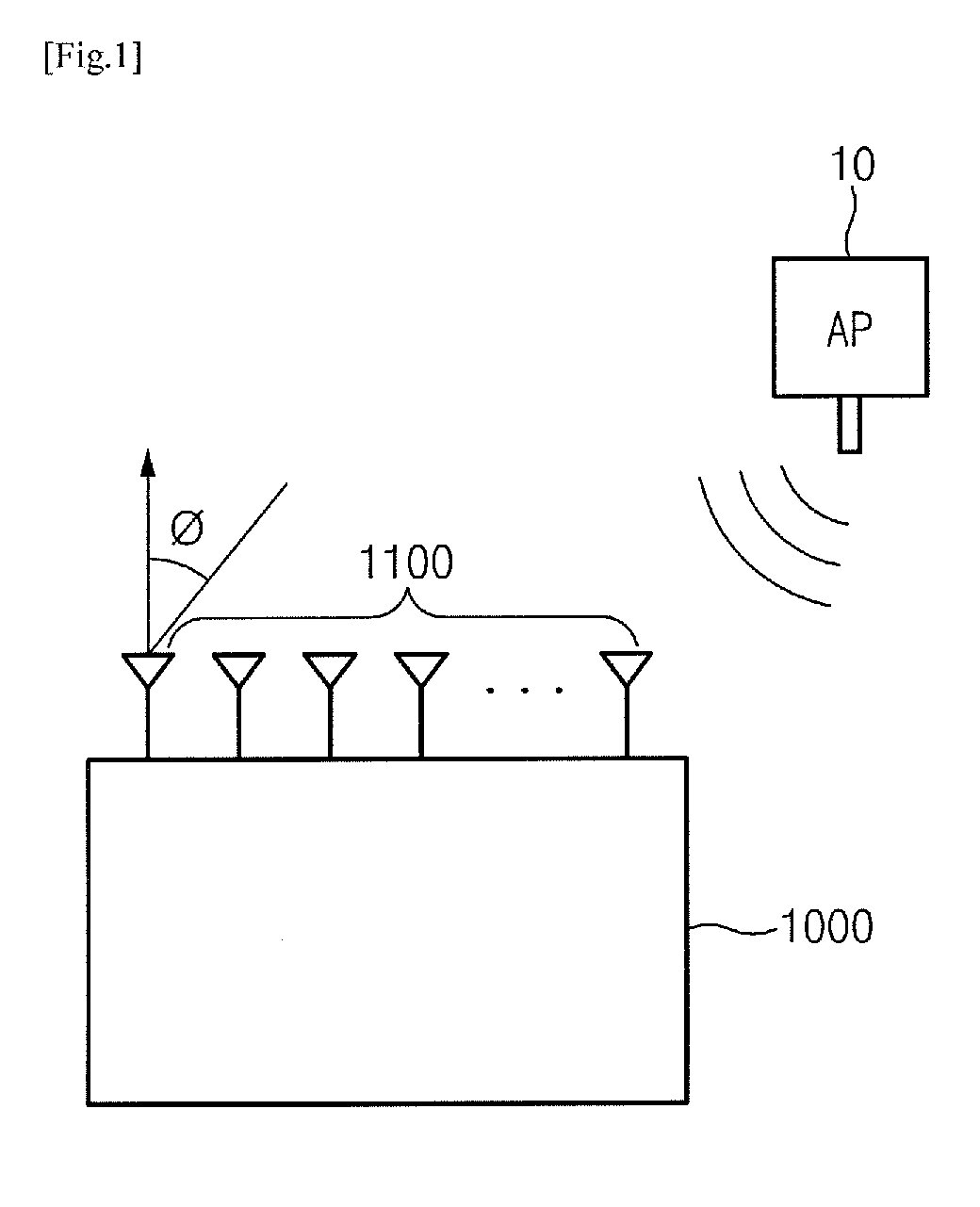
[0030]Hereinafter, some embodiments of the present invention will be described in detail with reference to the accompanying drawings. In the figures, even though the parts are illustrated in different drawings, it should be understood that like reference numbers refer to the same or equivalent parts. In describing the embodiments of the present invention, when it is determined that the detailed description of the known art related to the present invention may obscure the gist of the present invention, the detailed description thereof will be omitted.

[0031]In describing components of the exemplary embodiment of the present invention, terminologies such as first, second, A, B, (a), (b), and the like may be used. However, such terminologies are used only to distinguish a component from another component but a nature or an order of the component is not limited by the terminologies. If they are not contrarily defined, all terms used herein including technological or scientific terms have...


PUM


Abstract

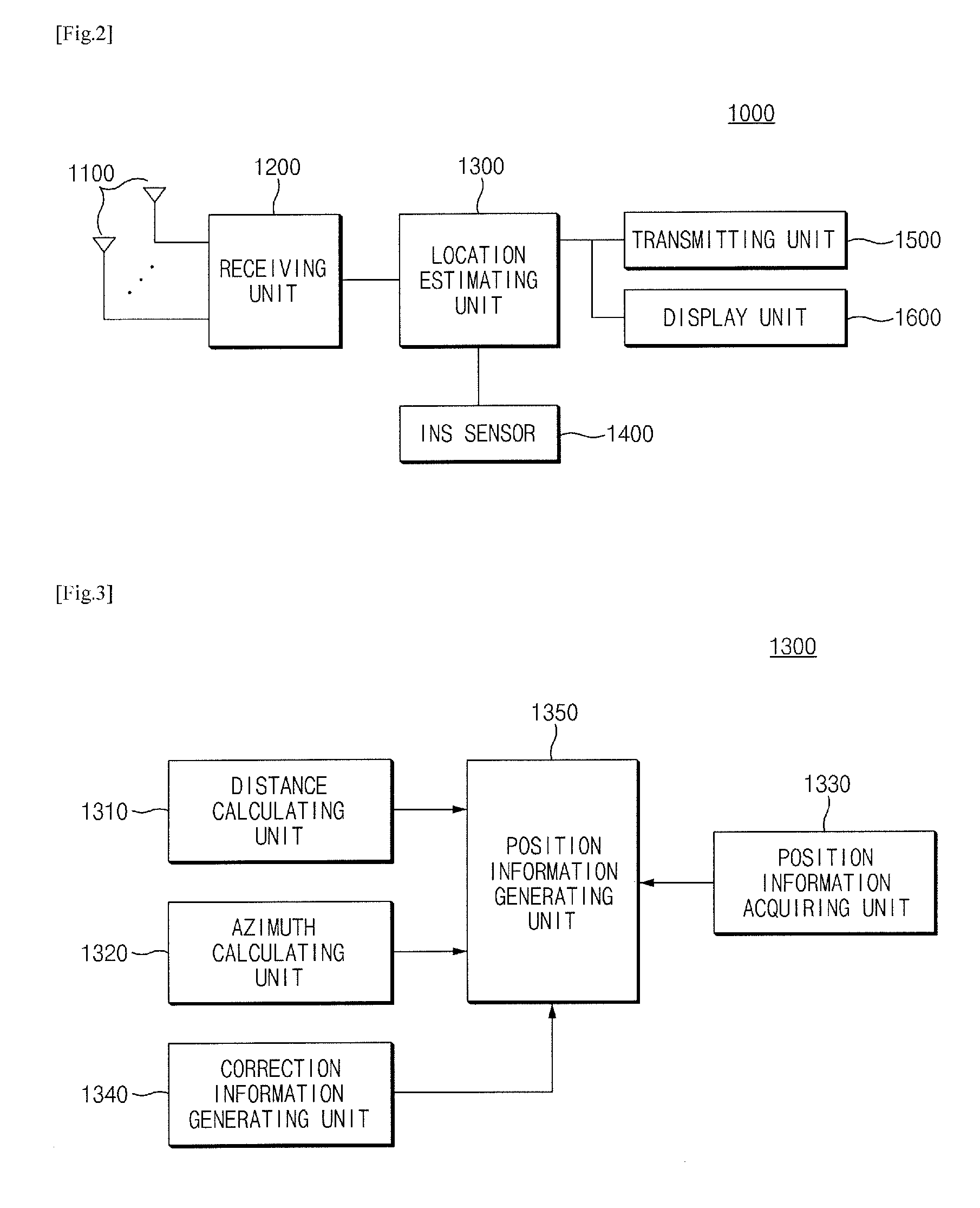
A location estimating apparatus according to an exemplary embodiment of the present invention is a location estimating apparatus which estimates a position of an electronic apparatus, including a distance calculating unit which calculates a distance from an AP using a strength (RSSI) of an AP signal which is received from the AP; an azimuth calculating unit which calculates an azimuth of the AP with respect to a reference direction using an entrance angle of the AP signal; a position information acquiring unit which acquires position information of the AP from the AP signal; a correction information generating unit which generates correction information based on detection information for movement of the electronic apparatus; and a position information generating unit which generates position information of the electronic apparatus using the distance from the AP and the azimuth based on the position information of the AP and corrects the position information of the electronic apparatus using the correction information.

Description

CROSS-REFERENCE TO RELATED APPLICATIONS[0001]This application claims priority to and the benefit of Korean Patent Application No. 10-2014-0087436 filed in the Korean Intellectual Property Office on Jul. 11, 2014, the entire contents of which are incorporated herein by reference.TECHNICAL FIELD[0002]The present invention relates to an apparatus and a method for estimating a location and an electronic apparatus including the apparatus.BACKGROUND ART[0003]As demands on a smart phone and a location based service using the smart phone are increased, demands on an indoor positioning technique which may precisely recognize a position of a terminal inside to reduce necessary expenses are increased. A general indoor positioning system is divided into a wireless AP method which provides a dedicated wireless access point (AP) such as WiFi, UWB, ZigBee, or pseudolite to use information from the AP, a method of using a mobile communication base station signal, and a method which uses a sensor in...

Claims


Application Information

Patent Timeline
Patent Type & Authority Applications(United States)
IPC IPC(8): G01S5/00G01S5/02
CPCG01S5/0284G01S5/0063G01S5/0236G01S5/12G01S5/02585
Inventor KIMKIM, JAE HOONSIN, CHEON SIGLEE, SANG UK
Owner ELECTRONICS & TELECOMM RES INST
Learn More