Eureka AIR delivers breakthrough ideas for toughest innovation challenges, trusted by R&D personnel around the world.

Endoscope with Pupil Expander

a technology of endoscope and expander, which is applied in the field of endoscope with expander, can solve the problems of difficult assembly and alignment, high manufacturing cost, and the inability to economically or technically feasible stereo endoscopes having two optical systems for certain applications

Inactive Publication Date: 2016-01-07
STERIS INSTR MANAGEMENT SERVICES INC
View PDF9 Cites 7 Cited by
  • Summary
  • Abstract
  • Description
  • Claims
  • Application Information

AI Technical Summary

Benefits of technology

The patent describes a technique for improving the stereoscopic effect of an endoscopic image by using a special prism block that separates the left and right halves of the entrance pupil and expands the distance between the optical axes of the two halves. This allows the endoscope to adapt to the optical axes of any stereo endoscope camera. The prism block can also be used to separate the exit pupil of the endoscope in a left and right half and expand the distance between the optical axes. This improves the overall quality and realism of the endoscopic image.

Problems solved by technology

However, with an increasing number of complex surgical procedures being performed and observed through endoscopes, the control of the position of endoscopic instruments has become more crucial for some surgeries.
Stereo endoscopes typically include two optical systems that are difficult to assemble and align and expensive to manufacture.
For these reasons, stereo endoscopes having two optical systems are not economically or technically feasible for certain applications.

Method used


Image

  • Endoscope with Pupil Expander
  • Endoscope with Pupil Expander
  • Endoscope with Pupil Expander

Examples


Embodiment Construction

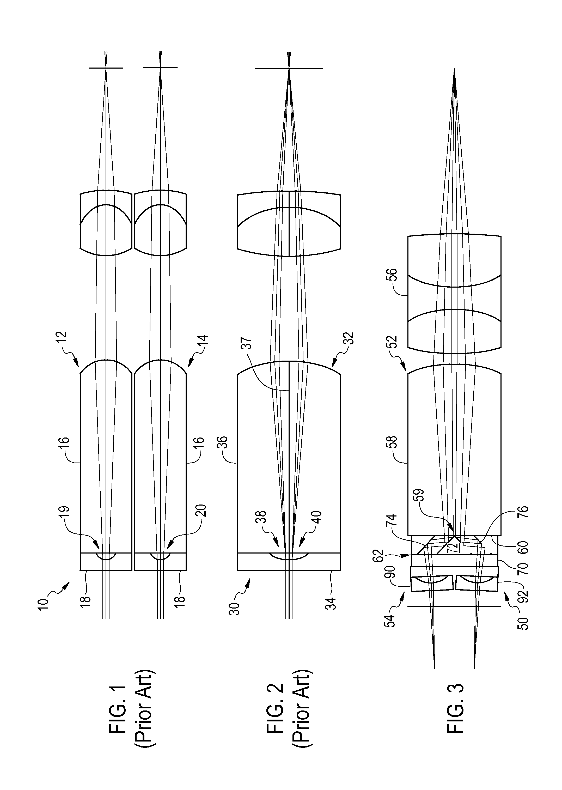
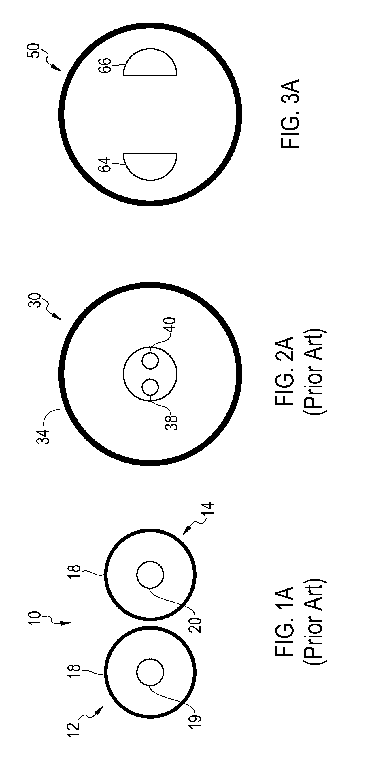
[0029]As described above, prior art stereo endoscope optical systems present in two basic configurations including those with two optical systems and those with a single optical system. Referring to FIG. 1, there is depicted a stereo endoscope optical system 10 including two separate optical systems or trains 12, 14. Each of optical systems 12, 14 includes a negative front lens 18 cemented to a plano surface of a plano-convex lens 16 of an objective. As depicted in FIGS. 1 and 1A, use of two separate optical systems 12, 14 provides stereo endoscope optical system 10 with two circular entrance pupils including a left entrance pupil 19 and a right entrance pupil 20 having an extended distance there between. A benefit of stereo endoscope optical system 10 is that it provides adequate right and left perceptive views of the object or working field. A shortcoming of stereo endoscope optical system 10 is that the diameter of the distal end of an endoscope must be great enough to accommodat...


PUM


Abstract

Disclosed are stereo endoscopes where the optical train of one optical system is separated in a left and right optical train. The separation in a left and right optical train is achieved by splitting the entrance pupil in a left and right pupil half. To additionally achieve a significant stereoscopic disparity the distance between the left and right pupil half is expanded. The separation of the entrance pupil and the expansion of the left and right pupil half is achieved by a distally located prism block. This prism block consists of a pair of rhomboidal prisms which are located exactly at the entrance pupil inside the endoscope objective. The front lens group is replaced by an identical pair of front lens groups each assembled in front of one of the two rhomboidal prisms. Such stereo endoscopes with expanded pupil halves enable to build stereo endoscopes with very small diameter or stereo endoscopes for special surgical applications. The described stereo endoscopes also include video endoscopes where the aperture functioning as the entrance pupil is separated in two halves and expanded for better stereoscopic effect. The prism block of the disclosed stereo endoscopes can also be used to separate the exit pupil of the disclosed stereo endoscopes and expand the optical axes on the proximal side to adapt to different stereo endoscopic cameras.

Description

FIELD OF THE INVENTION [0001]The present invention is directed to an optical system for an endoscope. More particularly, the present invention is directed to an optical system for a monoscopic endoscope, the optical system including a pupil expander assembly for creating two stereoscopic images.[0002]BACKGROUND OF INVENTION[0003]Technical and medical endoscopes are delicate optical instruments that are introduced in technical and human cavities to inspect the interior of the cavities. Such endoscopes can be rigid endoscopes containing a lens system, flexible endoscopes containing a flexible image guiding bundle or video endoscopes.[0004]Endoscopes have a small diameter of a few millimeters and are often several hundreds of millimeter long. Endoscopes contain an outer tube and an inner tube. The space between the outer tube and the inner tube is filled with illumination fibers that guide externally created light inside the cavities. Inside the inner tube is an optical system that rel...

Claims


Application Information

Patent Timeline
Patent Type & Authority Applications(United States)
IPC IPC(8): A61B1/00G02B23/24A61B1/05G02B23/02
CPCG02B23/2415A61B1/00193G02B23/02A61B1/05G02B23/243A61B1/00096A61B1/002G02B27/0081
Inventor ZOBEL, JURGEN
Owner STERIS INSTR MANAGEMENT SERVICES INC
Why Eureka
Eureka Blog
Learn More