
Filter and Blower Geometry for Particle Sampler

Active Publication Date: 2016-01-07
PARTICLE MEASURING SYST
View PDF3 Cites 20 Cited by
  • Summary
  • Abstract
  • Description
  • Claims
  • Application Information

AI Technical Summary

Benefits of technology

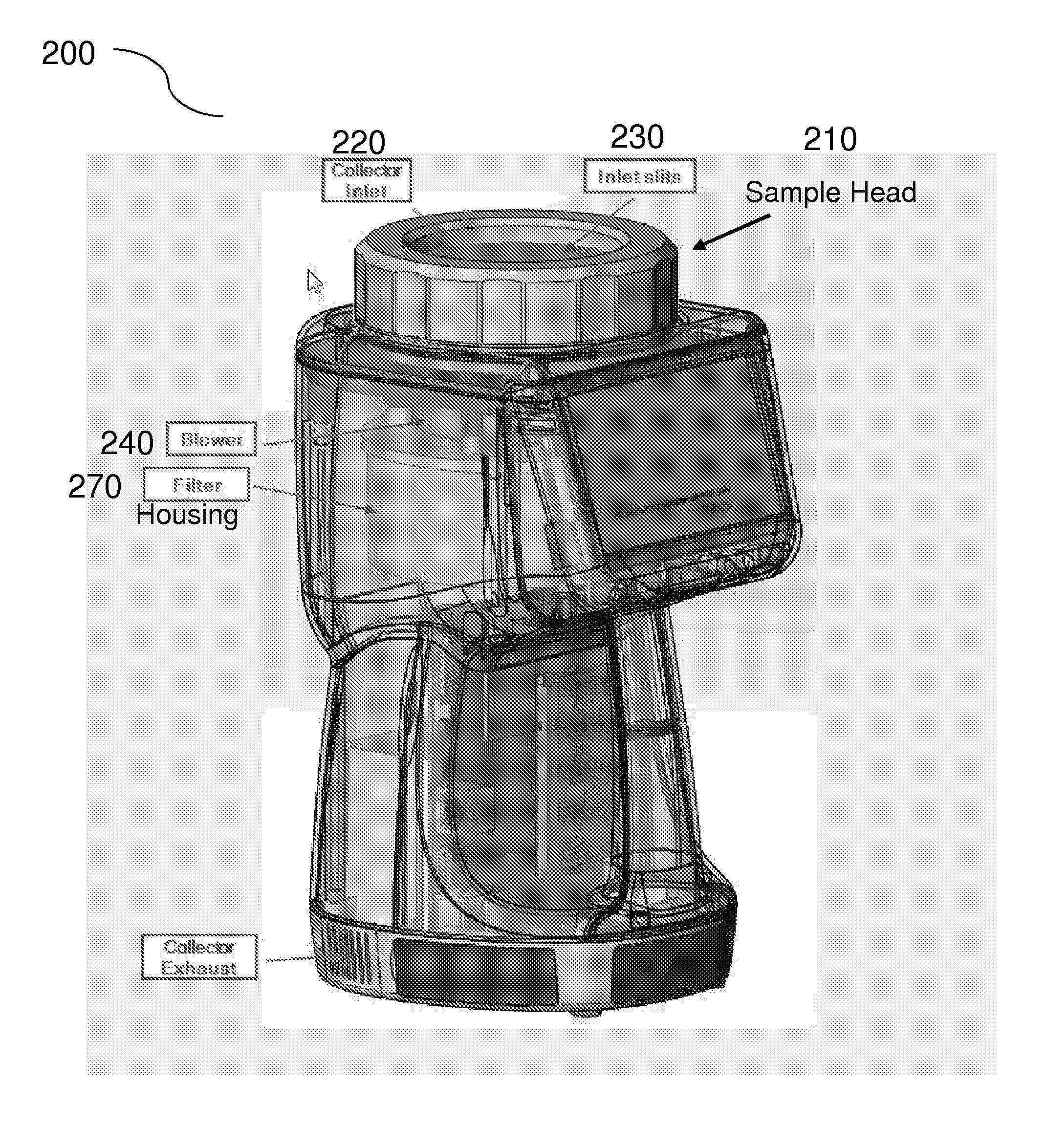
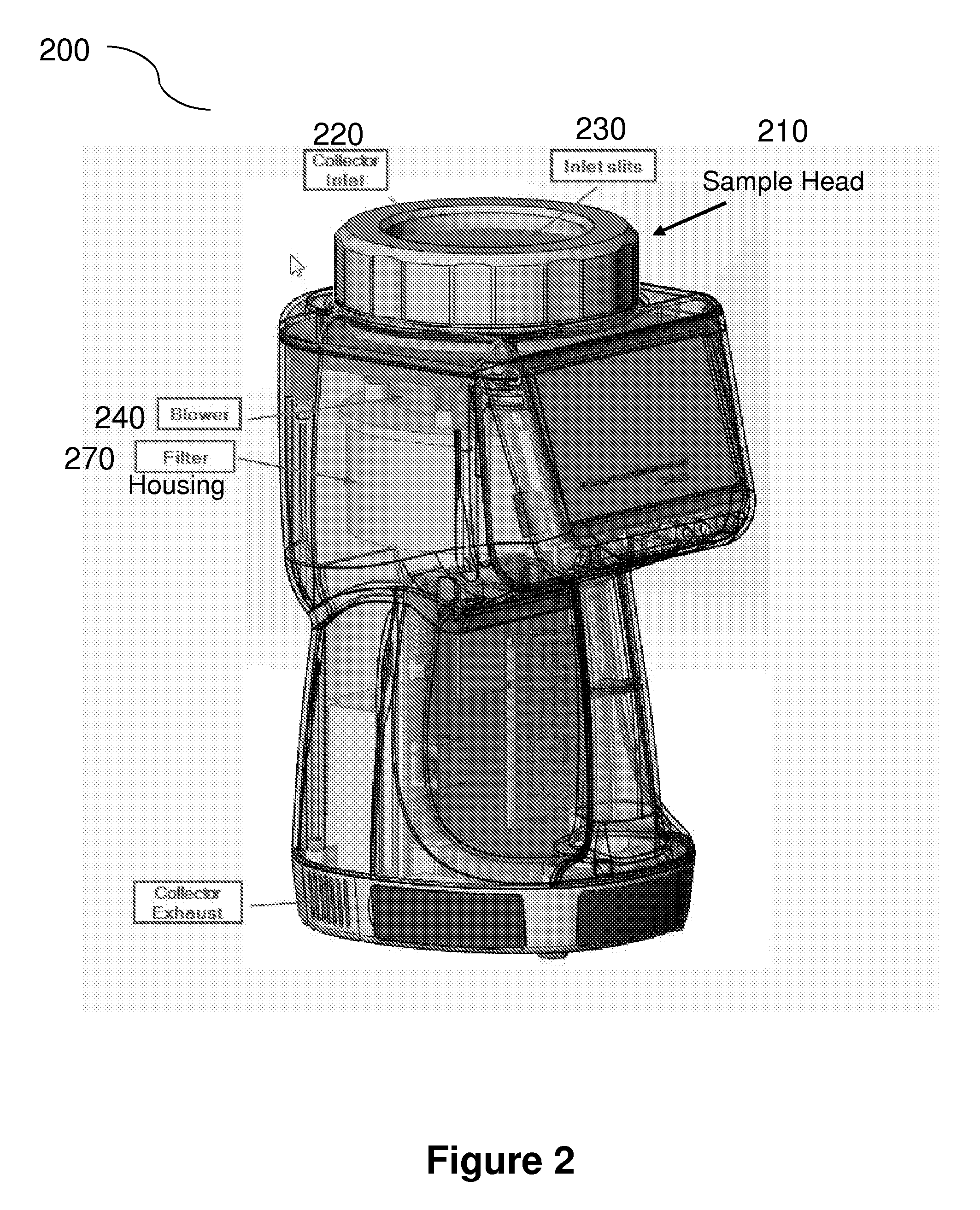
The invention provides devices and methods for sampling, detecting, and characterizing particles. The devices include a filter component to remove particles from the exhaust flow, which is useful in monitoring particles in manufacturing environments that require low levels of particles. The device has a compact form factor and a filter a temperature cooling effect that increases the operational lifetime of the motor. This compact and efficient device can be easily transported and handled for various applications, such as portable particle sampling and counting.

Problems solved by technology

For the semiconductor industry, an increase in airborne particulate concentration can result in a decrease in fabrication efficiency, as particles that settle on semiconductor wafers will impact or interfere with the small length scale manufacturing processes.
For the pharmaceutical industry, where this type of real-time efficiency feedback is lacking, contamination by airborne particulates and biological contaminants puts pharmaceutical products at risk for failing to meet cleanliness level standards established by the Food and Drug Administration (FDA).
For example, the collection efficiency may be of high importance, as failing to detect that biological particles are present in cleanroom air can result in the cleanroom environment having higher levels of contamination than detected.
Upon determination that under counting has occurred, pharmaceutical products made in those environments can be identified as failing to meet required standards, potentially leading to costly product recalls.
Similarly, failing to ensure that the viability of collected biological particles is maintained during the collection process will also result in under counting.
Such a situation can arise, for example, if the collected biological particles are destroyed, damaged or otherwise rendered non-viable upon impact with the growth medium, such that the collected particles do not replicate during the incubation process and, therefore, cannot be subsequently identified.
Over counting of this nature arises where a biological particle that is not collected from the cleanroom air, but is otherwise placed in contact with the growth medium, is allowed to replicate during the incubation process and is improperly identified as originating from the cleanroom air.
Situations that contribute to false positives include failing to properly sterilize the growth medium and collection system prior to particle collection and improper handling of the growth medium by cleanroom personnel as it is installed into a particle collection system and / or removed from the particle collection system and placed into the incubator.
Again, this can result in a pharmaceutical product being identified as failing to meet required standards.
Without sufficient measures to identify false positives, such a situation can result in pharmaceutical products that actually meet the required standards, but are destroyed due to an overestimation of biological particle concentration in the cleanroom air indicating that the standards were not met.

Method used


Image

  • Filter and Blower Geometry for Particle Sampler
  • Filter and Blower Geometry for Particle Sampler
  • Filter and Blower Geometry for Particle Sampler

Examples


Embodiment Construction

[0031]In general, the terms and phrases used herein have their art-recognized meaning, which can be found by reference to standard texts, journal references and contexts known to those skilled in the art. The following definitions are provided to clarify their specific use in the context of the invention.

[0032]“Particle” refers to a small object which is often regarded as a contaminant. A particle can be any material created by the act of friction, for example when two surfaces come into mechanical contact and there is mechanical movement. Particles can be composed of aggregates of material, such as dust, dirt, smoke, ash, water, soot, metal, minerals, or any combination of these or other materials or contaminants. “Particles” may also refer to biological particles, for example, viruses, spores and microorganisms including bacteria, fungi, archaea, protists, other single cell microorganisms and specifically those microorganisms having a size on the order of 1-20 μm. Biological parti...


PUM


Abstract

The invention provides devices and methods for sampling, detecting and / or characterizing particles. Devices and methods of the invention, including particle samplers, impactors and counters, include a filter component for removing particles in the exhaust flow of the device, for example, to eliminate or minimize the potential for the device itself to provide source of particles in an environment undergoing particle monitoring. This aspect of the present devices and methods is particularly useful for monitoring particles in manufacturing environments requiring low levels of particles, such as cleanroom environments for electronics manufacturing and aseptic environments for manufacturing pharmaceutical and biological products.

Description

CROSS-REFERENCE TO RELATED APPLICATIONS[0001]This application claims the benefit of and priority to U.S. Provisional Application No. 61 / 953,101, filed on Mar. 14, 2014, which is hereby incorporated by reference in its entireties to the extent not inconsistent herewith.STATEMENT REGARDING FEDERALLY SPONSORED RESEARCH OR DEVELOPMENT[0002]Not applicable.BACKGROUND OF INVENTION[0003]The invention is in the field of particle sampling, collection and analysis. The invention relates generally to devices and methods for sampling and characterizing particles in fluids include air and process chemicals (e.g., gases and liquids) for applications including the evaluation of contaminants in a range of cleanroom and manufacturing environments.[0004]Cleanrooms and clean zones are commonly used in semiconductor and pharmaceutical manufacturing facilities. For the semiconductor industry, an increase in airborne particulate concentration can result in a decrease in fabrication efficiency, as particle...

Claims


Application Information

Patent Timeline
IPC IPC(8): C12Q1/24G01N1/14G01N15/14
CPCC12Q1/24G01N15/1434G01N1/14G01N1/2205G01N1/2208G01N1/2273G01N15/0606G01N2001/2223G01N2001/245
Inventor KETCHAM, CLIFFHARTIGAN, PAUL B.ADKINS, RONALD W.
Owner PARTICLE MEASURING SYST
Learn More