
Aerosolization system with flow restrictor and feedback device

a technology of flow restrictor and feedback device, which is applied in the direction of inhalator, medical device, other medical devices, etc., can solve the problems of medicament contamination by the user or other sources, medicament contamination is particularly problematic, and the force of aerosolized medicament is often too great or too little,

Active Publication Date: 2016-01-07
AERAMI THERAPEUTICS INC
View PDF7 Cites 34 Cited by
  • Summary
  • Abstract
  • Description
  • Claims
  • Application Information

AI Technical Summary

Benefits of technology

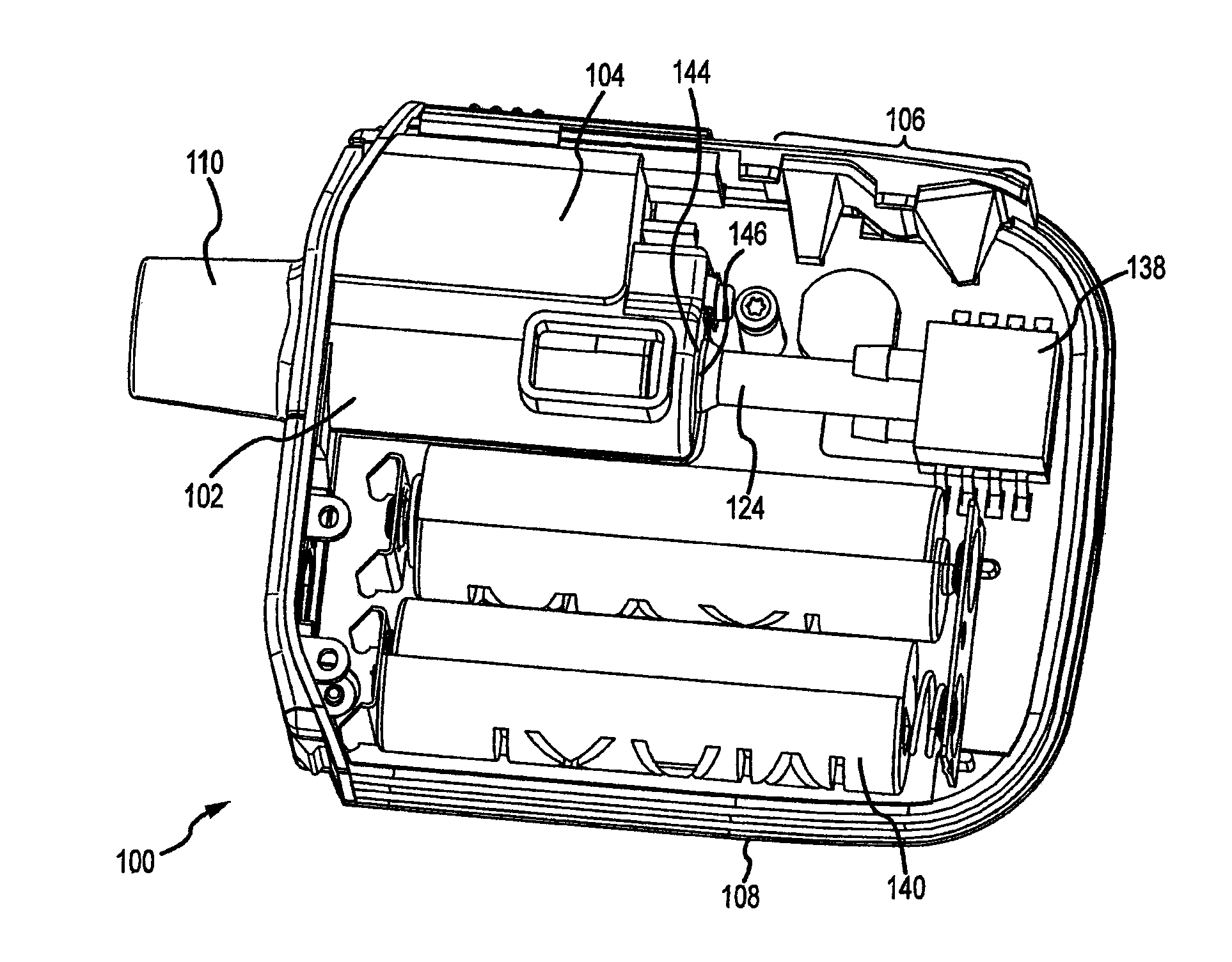
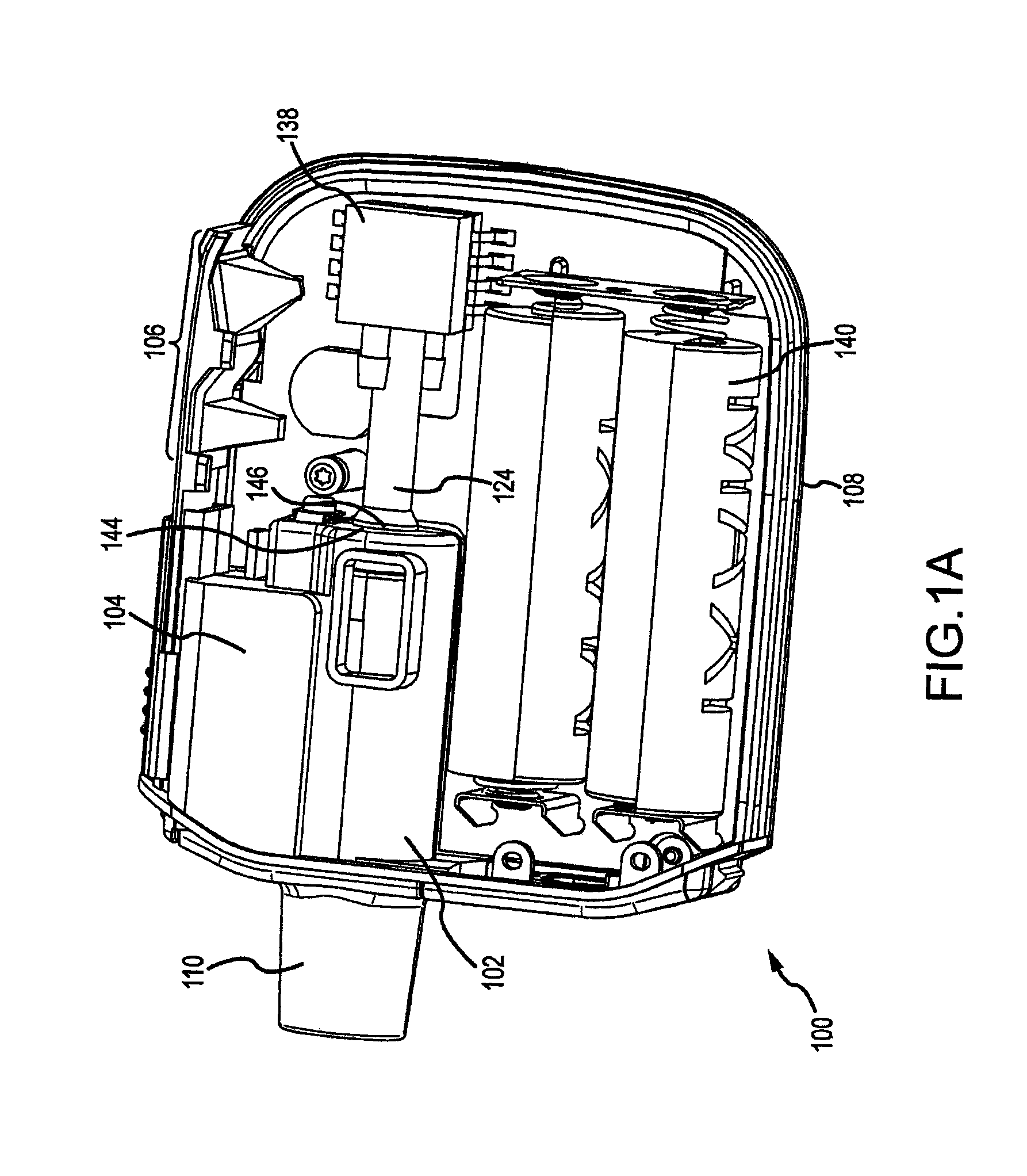
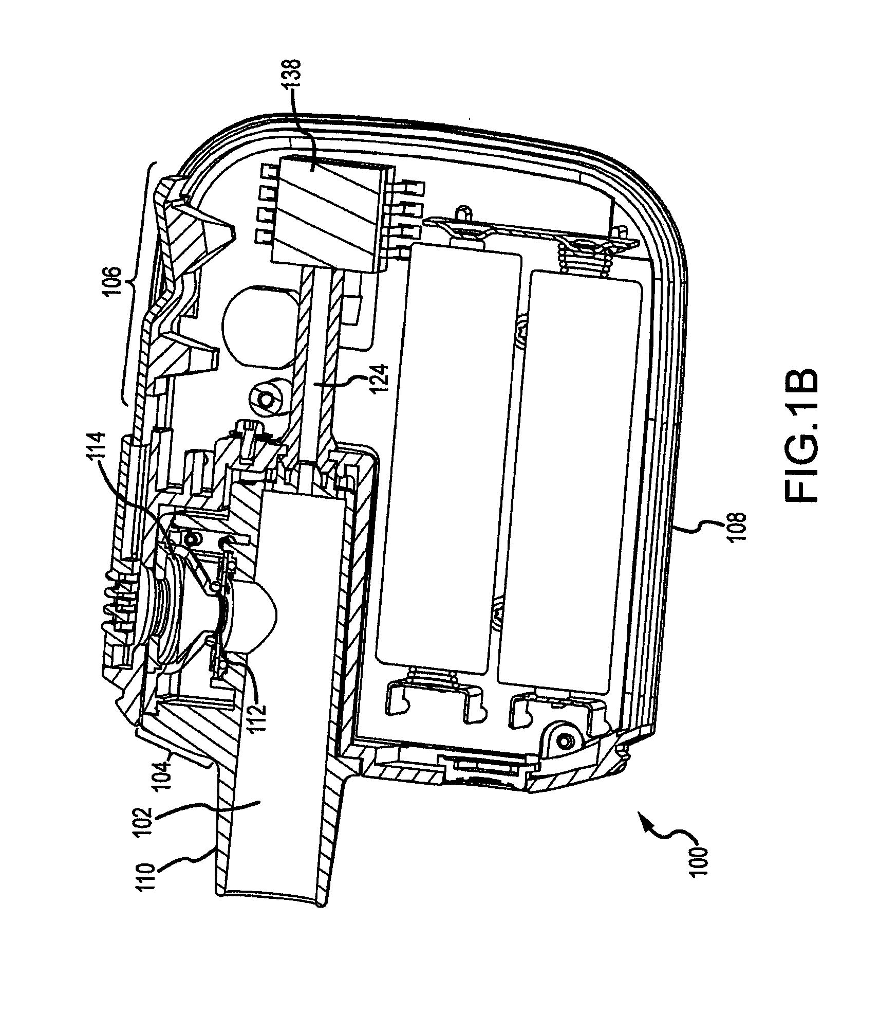
This patent describes an aerosolization device designed to deliver medicine properly into a person's breathing system. It includes a tube, a part called an aerosolizer, a component called a restrictor, and something called an indicator mechanism. The tube has a mouthpiece at its other end where air flows when someone takes a deep breath. The aerosolizer generates the mist-like medicine. The restrictor has small openings that help create more pressure difference between what happens before and after it than there would otherwise be if no restrictions were present. This results in smoother and easier breathing of the medicine. The indicator mechanism lets users know how well their breathing is doing compared to a target level.

Problems solved by technology

This patent discusses issues with existing aerosolization systems that can result in inconsistent dosing, poor absorption of medicine, and potential contamination. The technical problem addressed by this patent is how to create an improved aerosolization system that overcomes these challenges and delivers precise and safe dosages of medicine to users.

Method used


Image

  • Aerosolization system with flow restrictor and feedback device
  • Aerosolization system with flow restrictor and feedback device
  • Aerosolization system with flow restrictor and feedback device

Examples


Embodiment Construction

[0018]The ensuing description provides exemplary embodiments only, and is not intended to limit the scope, applicability or configuration of the invention. Rather, the ensuing description of exemplary embodiments will provide those skilled in the art with an enabling description for implementing various embodiments of the invention. It will be understood that various changes may be made in the function and arrangement of elements without departing from the spirit and scope of the invention as set forth in the appended claims. For example, any detail discussed with regard to one embodiment may or may not be present in variations of that embodiment, and / or in other embodiments discussed herein.

[0019]Embodiments of an aerosolization device for assisting in proper delivery of an aerosolized medication to a user's respiratory system are described herein. In many embodiments, liquid medicament may be provided to an aerosolization device in a metered dose. The liquid medicament may be disp...


PUM


Abstract

In one aspect, embodiments of the present invention provide an aerosolization device for ensuring proper delivery of an aerosolized medication to a user's respiratory system. The aerosolization device may include a conduit, an aerosol generator, a restrictor disposed within the conduit, and an indicator mechanism. The conduit may include a mouthpiece end by which a user may cause inspiratory flow through the conduit. The aerosol generator may include a vibratable mesh. The restrictor may define a plurality of apertures disposed along an outer periphery of the restrictor configured to provide an increase in pressure differential that varies with an inspiratory flow rate within the conduit and to provide a relatively laminar flow downstream of the restrictor compared to upstream of the restrictor. The indicator mechanism may indicate to a user a state of a parameter of the inspiratory flow relative to a predefined desired range.

Description


Claims


Application Information

Patent Timeline
Owner AERAMI THERAPEUTICS INC
Learn More