
Juice Extractor

a juice extractor and juice technology, applied in the direction of strainers, centrifuges, kitchen equipment, etc., can solve the problems of limited use of juice extractors to smaller diameter foodstuffs, potential serious injuries, and difficult operation,

Inactive Publication Date: 2016-01-07
HAMILTON BEACH BRANDS
View PDF5 Cites 6 Cited by
  • Summary
  • Abstract
  • Description
  • Claims
  • Application Information

AI Technical Summary

Benefits of technology

The patent text is talking about a new type of juice extractor with a big food chute. The problem is that this new extractor doesn't have any barriers or interlock mechanisms to keep users safe from injury. So, the technical effect of the patent text is to provide a safer and more efficient way to extract juice from fruits and vegetables.

Problems solved by technology

The UL standard requires such combination of dimensions because it has found that the combination of a 3″ diameter and a 4″ length will generally prevent an average adult's hand from extending far enough into the food chute to contact the grating blade, which would otherwise result in potentially serious injury.
However, one drawback of such relatively small sized food chutes is the limitation of use of the juice extractor to smaller diameter foodstuff or to passing the foodstuff through the food chute in a limited quantity.
This process can be particularly cumbersome and time-consuming, especially when the user wishes to produce a larger amount of juice.
Such barrier structures are not without drawbacks, however.
Further, the barrier structure often poses cleaning challenges due to the increase in parts and thus the increase in locations for food to get stuck.
Yet further, as the barrier structure is an additional movable operating part, juice extractors having such a barrier structure generally make more noise and / or vibrations during operation than juice extractors without such barrier structures and are potentially more susceptible to breakage and / or malfunction.
These drawbacks can also be cumbersome for users.

Method used


Image

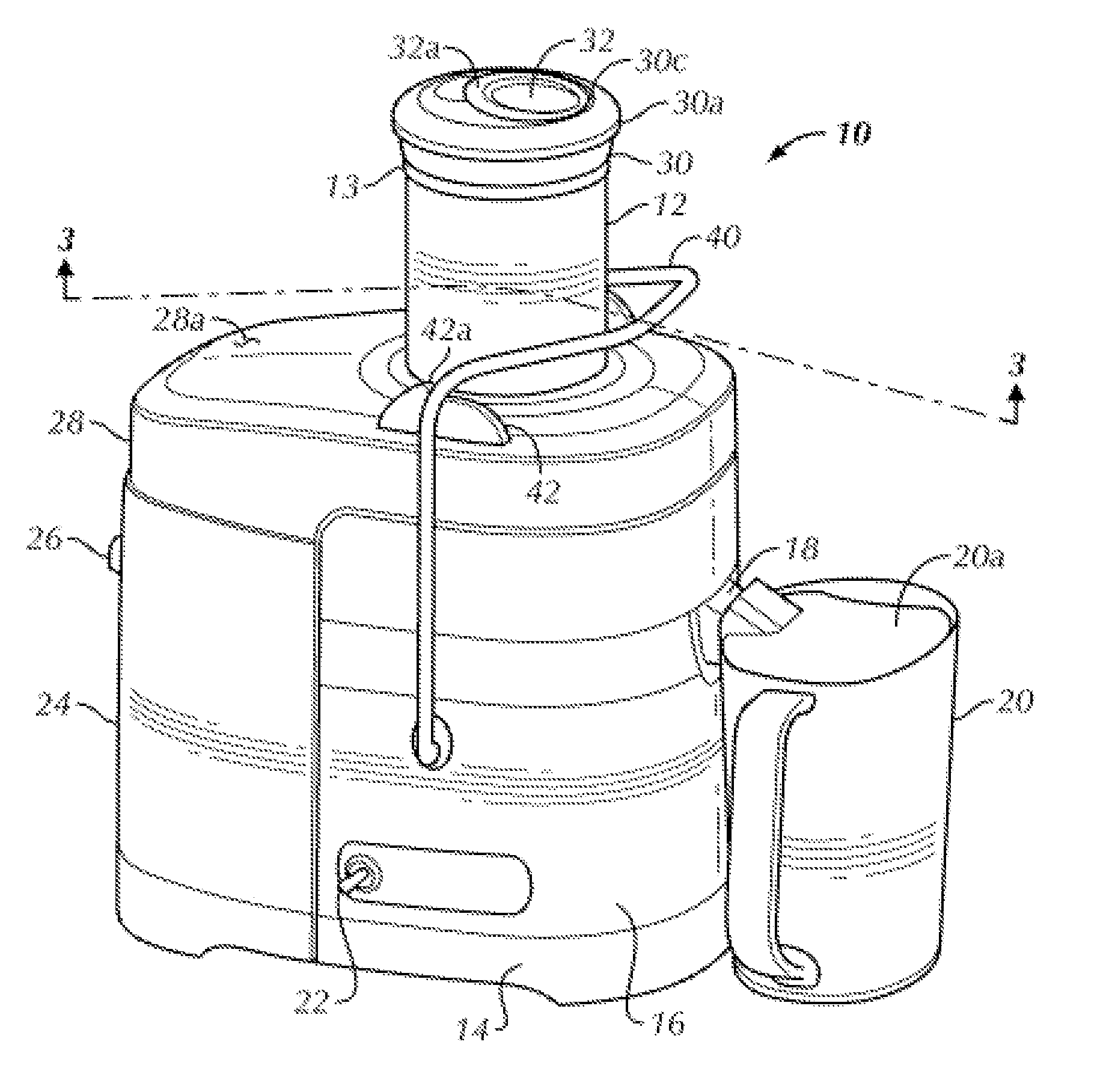
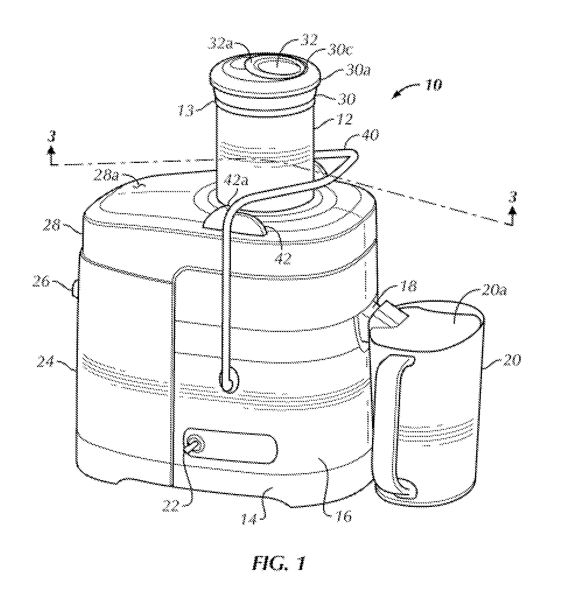
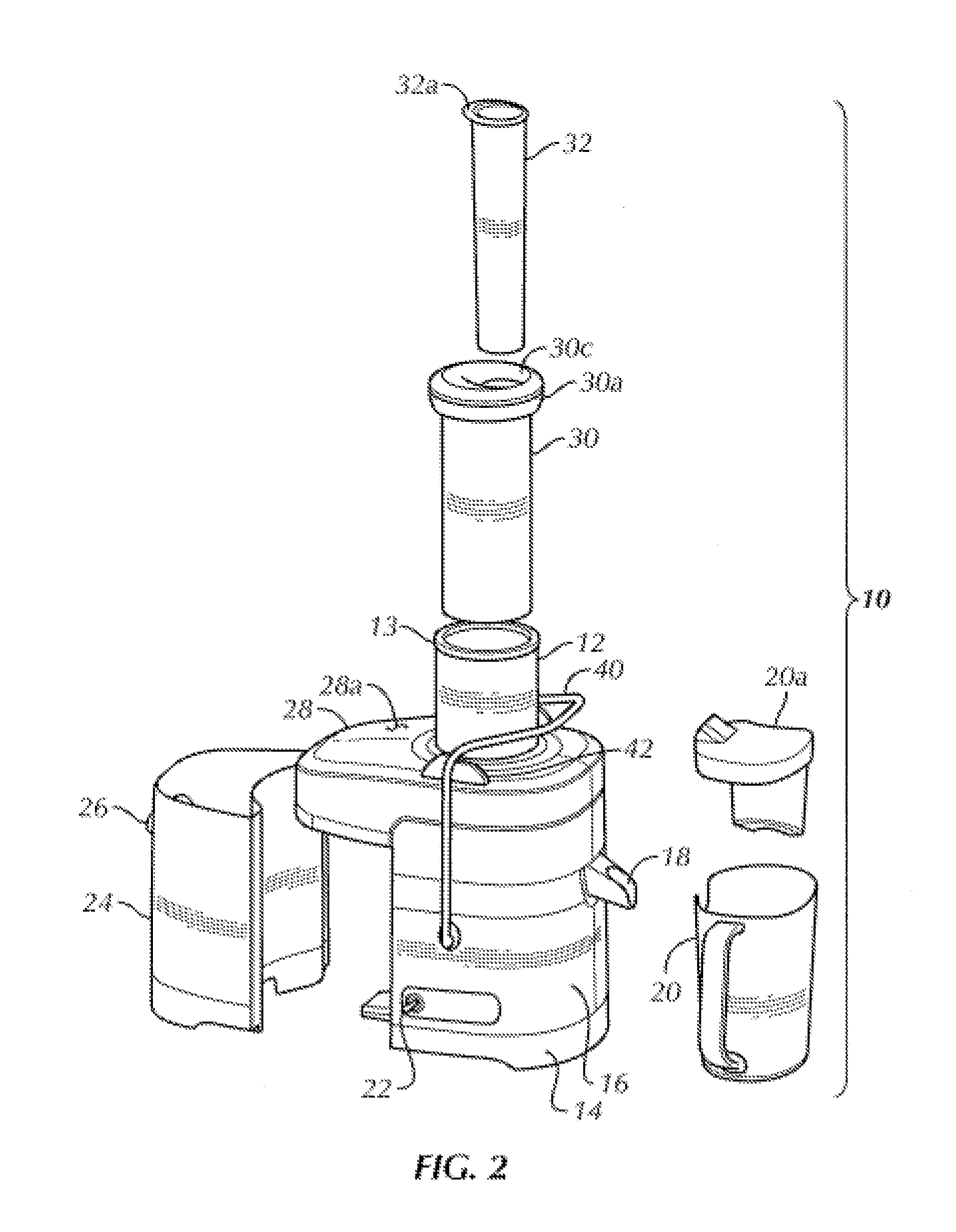
  • Juice Extractor
  • Juice Extractor
  • Juice Extractor

Examples


Embodiment Construction

[0014]Certain terminology is used in the following description for convenience only and is not limiting. The words “lower,”“bottom,”“upper” and “top” designate directions in the drawings to which reference is made. The words “inwardly,”“outwardly,”“upwardly” and “downwardly” refer to directions toward and away from, respectively, the geometric center of the juice extractor, and designated parts thereof, in accordance with the present disclosure. Unless specifically set forth herein, the terms “a,”“an” and “the” are not limited to one element, but instead should be read as meaning “at least one.” The terminology includes the words noted above, derivatives thereof and words of similar import.

[0015]It should also be understood that the terms “about,”“approximately,”“generally,”“substantially” and like terms, used herein when referring to a dimension or characteristic of a component of the disclosure, indicate that the described dimension / characteristic is not a strict boundary or param...


PUM


Abstract

A juice extractor includes a housing, a lid for covering the housing and enclosing an interior thereof and a generally cylindrical food chute projecting into the housing through the lid. The chute defines an unrestricted interior channel from an open upper end thereof to an open base end thereof for receiving and passing foodstuff therethrough. The chute has an internal diameter of approximately three and a half inches and a length from the upper end to the base end of at least approximately eight inches. A food pusher is slidably receivable within the interior channel of the chute and is movable between a disengaged position, wherein the food pusher is not engaged with the chute and the interior channel remains unrestricted and continuously open between the upper end and the base end, and an engaged position, wherein the food pusher is slidably received within the interior channel of the chute.

Description

CROSS-REFERENCE TO RELATED APPLICATIONS[0001]This application claims priority to U.S. Provisional Patent Application No. 62 / 019,941, filed on Jul. 2, 2014, entitled “Juice Extractor,” the entire contents of which are incorporated by reference herein.FIELD OF THE DISCLOSURE[0002]The present disclosure is generally directed to a juice extractor, and, more particularly, to a juice extractor having a large food chute to facilitate the passage of larger foodstuff therethrough but that does not contain an interlock mechanism in the food chute.BACKGROUND[0003]Juice extractors are generally known in the small appliance art. Typically, juice extractors have food chutes that are no greater than 3″ in diameter and no less than 4″ in length, in order to comply with the Underwriters Laboratories (“UL”) safety standard requirements and suitably protect a consumer. The UL standard requires such combination of dimensions because it has found that the combination of a 3″ diameter and a 4″ length wil...

Claims


Application Information

Patent Timeline
IPC IPC(8): A23N1/02
CPCA23N1/02A47J19/06A47J19/00
Inventor CARLEY, MATTHEW, T.
Owner HAMILTON BEACH BRANDS
Learn More