
Rotor housing assembly for a harvester

Active Publication Date: 2016-01-07
BLUE LEAF I P +1
View PDF17 Cites 11 Cited by
  • Summary
  • Abstract
  • Description
  • Claims
  • Application Information

AI Technical Summary

Benefits of technology

The invention is a rotor housing assembly for a harvester that allows the movement of associated vanes without creating gaps between them and the inner surface of the cover plate, resulting in a more durable mechanism that improves the setting of the harvester and increases efficiency. The cover has reinforcement ribs on its outer surface to prevent deformation and ensure proper movement of crop material through the machine. This prevents the formation of gaps and clogging of the machine, making it easier to operate and produce more yield.

Problems solved by technology

A smaller vane pitch angle setting will reduce in the rearward speed of the flow of the crop material and will typically result in the crop material flowing in a correspondingly steeper or tighter helical path through that region of the threshing cage, and thus greater dwell time in the threshing part of the rotor for threshing and separating.
The disadvantage thereof is that the operator has to leave the cabin and wrench for about 20 minutes to change the position of the vanes.
Furthermore, the space between the grain tank and the rotor is not easily accessible and therefore the vanes are only changed in case of big issues as for instance losses of power.
The combine harvester consequently is not optimally used in terms of setting resulting in less efficiency and productivity.
This does not allow adjustment of the combine harvester on the go.
A problem that arises with the adjustment of the vanes is that the vanes seal against a cylindrically formed cover and thus have a certain curvature.
A first disadvantage thereof is that there is a risk that the vanes do not connect against the cylindrically formed cover, and thus gaps between the vanes and the cover occur which can become clogged because dirt can get stuck in these gaps through which it is more difficult or even impossible to move the vanes without these gaps previously being cleaned.
A second disadvantage thereof is that this deformation unwillingly can significantly change the material flow characteristics for this rotor section.
A first disadvantage thereof is that the length of straight vanes is very small and the impact on the transportation of the crop material throughout the rotors consequently is also smaller.
A second disadvantage thereof is that the fixed and the adjustable vanes do not form a continuous curve anymore and form gaps between these vanes into which crop material can get clogged.

Method used


Image

  • Rotor housing assembly for a harvester
  • Rotor housing assembly for a harvester
  • Rotor housing assembly for a harvester

Examples


Embodiment Construction

)

[0052]It is remarked that within this specification, for convenience, the terms “grain” and “straw” are used principally as it is to be understood that these terms are not intended to be limiting. “Grain” thus refers to that part of the crop material which is threshed and separated from the discardable part of the crop material which is referred to as “straw”. Also the terms “forward”, “rearward”, “left” and “right”, when used in connection with the harvester and / or components thereof are determined with reference to the direction of forward operative travel of the harvester, but again, they should not be construed as limiting. The terms “longitudinal” and “transverse” are determined with reference to the fore-and-aft direction of the harvester and are equally not to be construed as limiting.

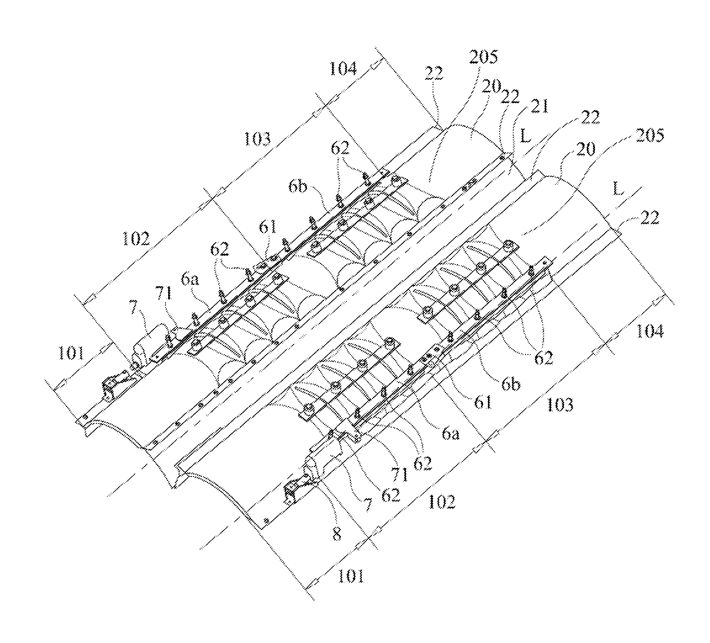
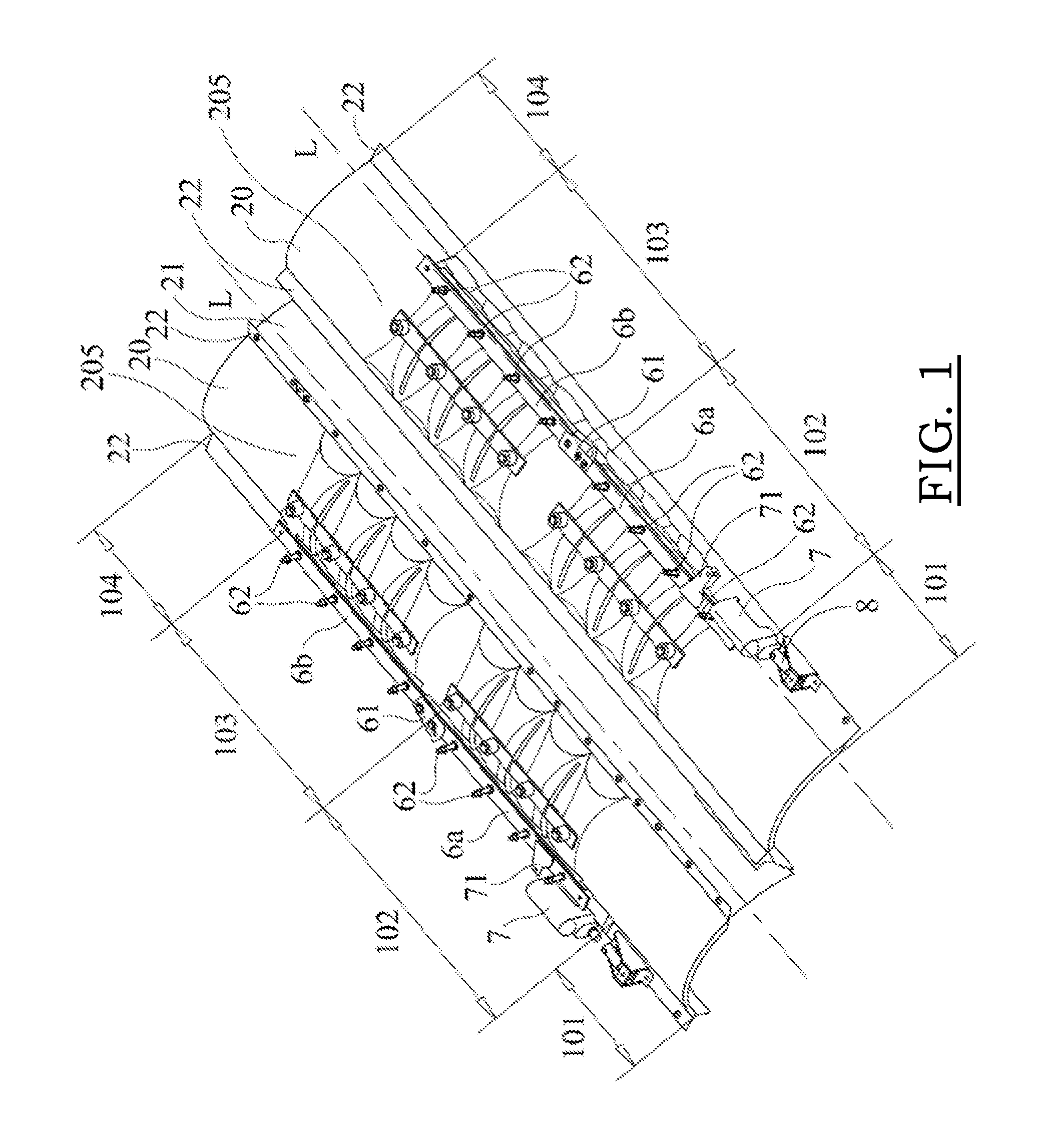
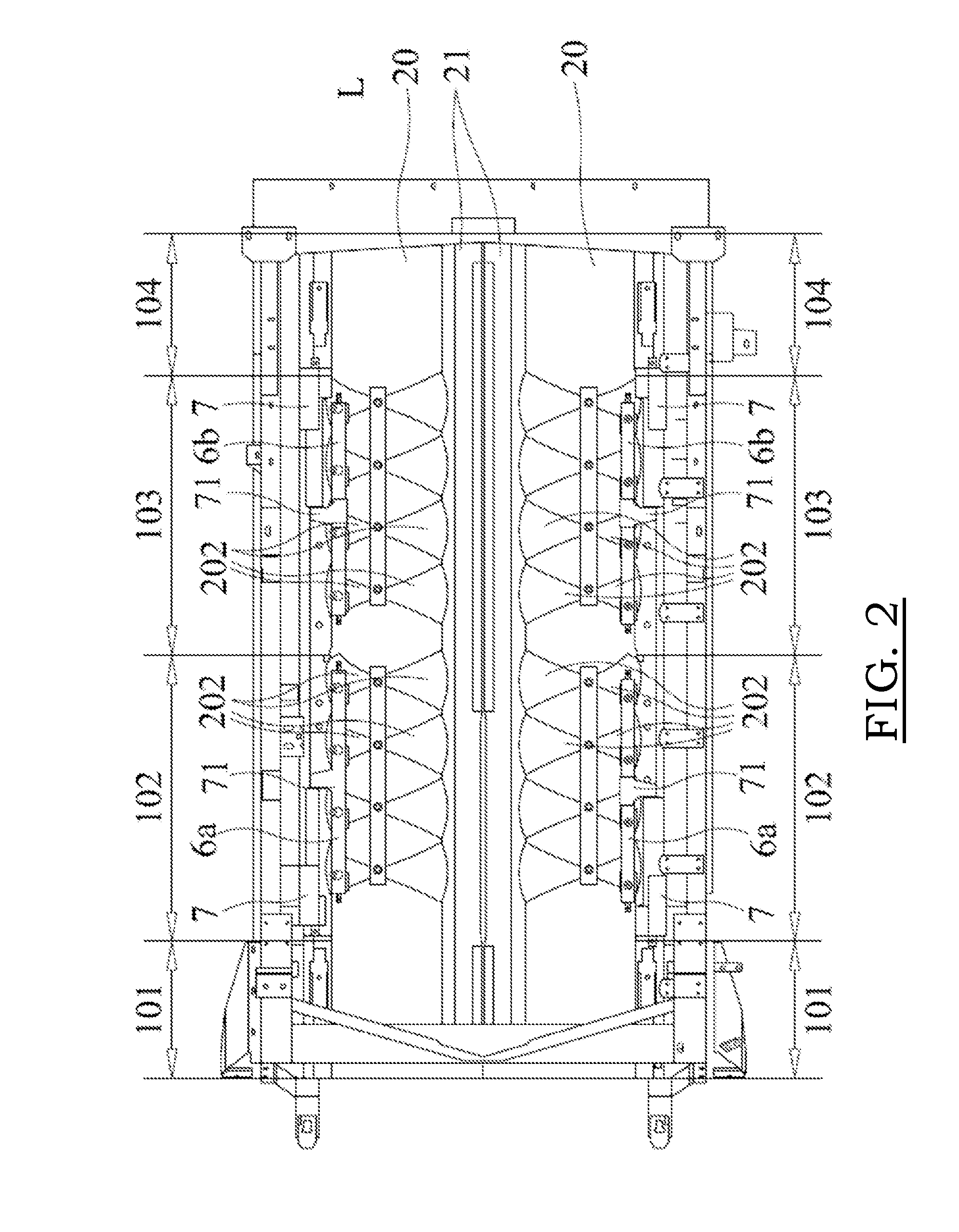
[0053]In the FIGS. 1 to 3, a rotor housing assembly (1) (hereafter further called ‘assembly’) of a twin axial rotor type harvester is shown. As can be seen in these figures, the assembly (1) co...


PUM


Abstract

The invention relates to a rotor housing assembly for a harvester, having at least one cover plate forming part of a generally cylindrical shaped rotor housing, a central longitudinal axis, and comprising an inner surface, which, when mounted, faces the central longitudinal axis and has a first radius, and one or more rotatable vanes which each are rotatably mounted on an inner surface of the cover plate facing the central longitudinal axis at a rotation point, the one or more rotatable vanes comprising a contact surface with the inner surface, the contact surface having a second radius being larger than the first radius of the cover plate, wherein the inner surface of the top cover plate, per rotatable vane, comprises a symmetrically curved shape such that, during a rotation of the respective vane, the contact surface of the vane with the inner surface of the cover plate substantially follows the shape of the inner surface.

Description

[0001]This application is the US National Stage filing of International Application Serial No. PCT / EP2014 / 054376 filed on Mar. 6, 2014 which claims priority to Belgian Application BE2013 / 0149 filed Mar. 7, 2013, each of which is incorporated herein by reference in its entirety.FIELD OF THE INVENTION[0002]The present invention relates to a rotor housing assembly for a harvester, comprising at least one cover plate having a generally curved shape, forming part of a generally cylindrical shaped rotor housing, a central longitudinal axis, and comprising an inner surface, which, when mounted, faces the central longitudinal axis and has a first radius, and a vane system comprising one or more rotatable vanes which each are rotatably mounted on the inner surface of the cover plate at a rotation point, the one or more rotatable vanes comprising a contact surface with the inner surface of the cover plate, the contact surface having a second radius being larger than the first radius.BACKGROUN...

Claims


Application Information

Patent Timeline
IPC IPC(8): A01F12/18A01D41/00A01F7/06
CPCA01F12/18A01F7/06A01D41/00A01F7/067
Inventor DUQUESNE, FRANK R.G.MAENHOUT, PHILIPMISSOTTEN, BART M.A.VAN DER HAEGEN, JOHAN A.
Owner BLUE LEAF I P
Learn More