
Systems and devices for sensing corrosion and deposition for oil and gas applications

a technology of system and device, applied in the direction of survey, instrument, borehole/well accessories, etc., can solve the problems of corroding conditions of tools and instruments used in oil and gas exploration and production, affecting the operation of tools, and corroding and degrading tools during us

Active Publication Date: 2015-12-31
BAKER HUGHES INC
View PDF3 Cites 28 Cited by
  • Summary
  • Abstract
  • Description
  • Claims
  • Application Information

AI Technical Summary

Benefits of technology

The present patent relates to wellbore sensing systems that use optical fibers and detect changes in the environment surrounding the fibers to sense and analyze conditions in oil and gas equipment. The systems include optical fibers with distal ends and proximal ends, and a mass of sensor material attached to the distal ends. The sensor material can detect changes in the distance between the optical fiber and the sensor material, resulting from the buildup of corrosion or deposition of material on the equipment. The systems can also include fiber Bragg gratings and a light wavelength sensor to detect changes in light reflected from the gratings. The technical effects of the patent are the development of improved systems for sensing conditions in oil and gas equipment, which can provide early detection of potential damage and facilitate timely maintenance and repair.

Problems solved by technology

Tools and instruments used for oil and gas exploration and production are often exposed to corrosive conditions, such as high temperatures, high pressures, reactive chemicals, and abrasive materials.
Therefore, these tools corrode and degrade during use.
In addition, scale (i.e., debris and materials from the wellbore or from fluids therein) may be deposited on tools used for exploration and production of oil and gas, which may foul the operation of the tools and create a flow restriction.

Method used


Image

  • Systems and devices for sensing corrosion and deposition for oil and gas applications
  • Systems and devices for sensing corrosion and deposition for oil and gas applications
  • Systems and devices for sensing corrosion and deposition for oil and gas applications

Examples


embodiment 1

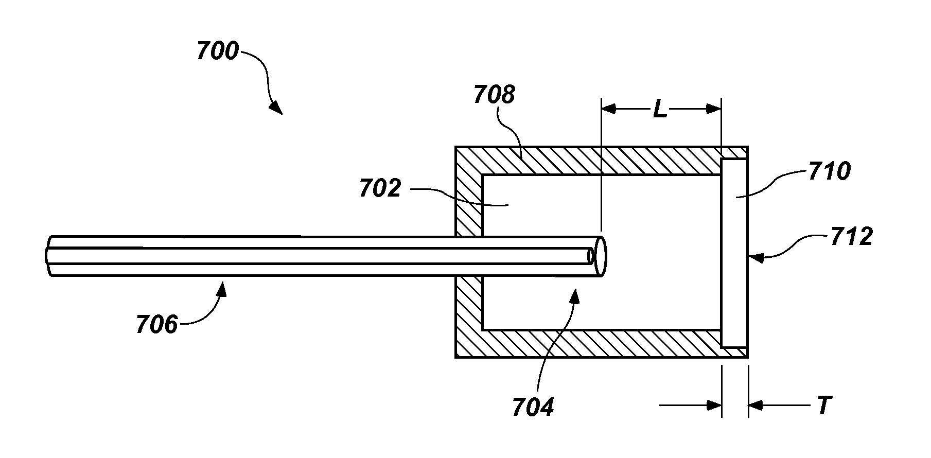
[0070]A wellbore sensing system, comprising: a tube defining a Fabry-Perot cavity; an optical fiber comprising a distal end disposed within the Fabry-Perot cavity and a proximal end opposite the distal end; a corrodible material capping the Fabry-Perot cavity; and an analysis module operatively coupled to the proximal end of the optical fiber, the analysis module configured to sense and analyze a difference of a light signal resulting from a change in a distance between the corrodible material and the distal end of the optical fiber due to a change in thickness of the corrodible material.

embodiment 2

[0071]The system of Embodiment 1, wherein the tube is positioned proximate a downhole component within a wellbore.

embodiment 3

[0072]The system of Embodiment 1 or Embodiment 2, wherein the distal end of the optical fiber is mounted to an electrical submersible pump.


PUM

PropertyMeasurementUnit
thicknessaaaaaaaaaa
lengthaaaaaaaaaa
thicknessaaaaaaaaaa

Abstract

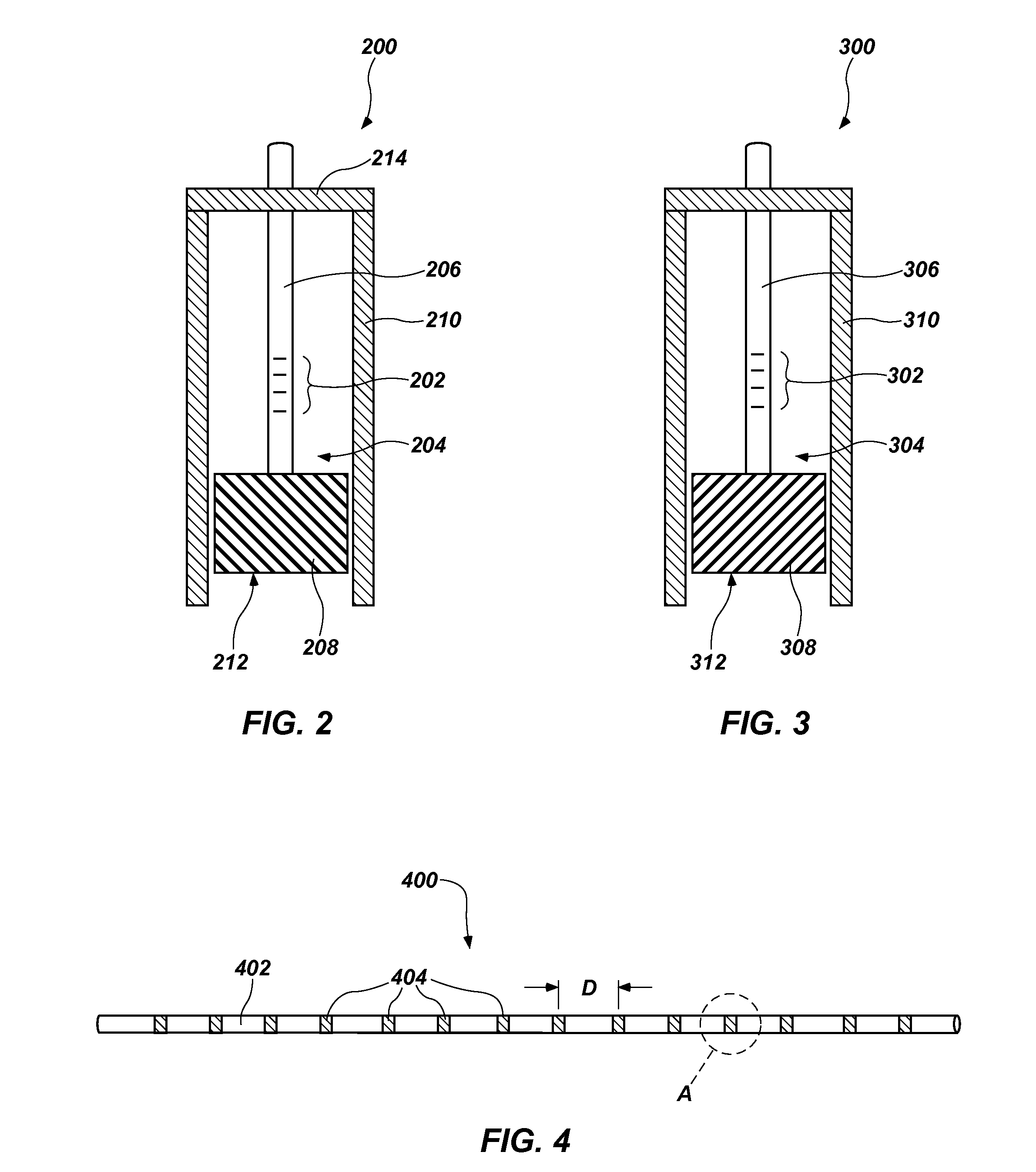
Sensing systems include a tube defining a Fabry-Perot cavity and an optical fiber including a distal end disposed within the Fabry-Perot cavity and a proximal end. A corrodible material caps the Fabry-Perot cavity. Devices for sensing corrosion of downhole equipment include an optical fiber with a corrodible material disposed over a distal end of the optical fiber. Systems for sensing a condition in equipment include an optical fiber with a fiber Bragg grating proximate a distal end thereof and a mass of sensor material coupled to the distal end of the optical fiber. The mass of sensor material is suspended from above the fiber Bragg grating. Other systems for sensing a condition in a wellbore include an optical fiber and a plurality of fiber Bragg gratings along a length thereof. A plurality of sensor materials are coupled to the optical fiber and surround respective fiber Bragg gratings.

Description

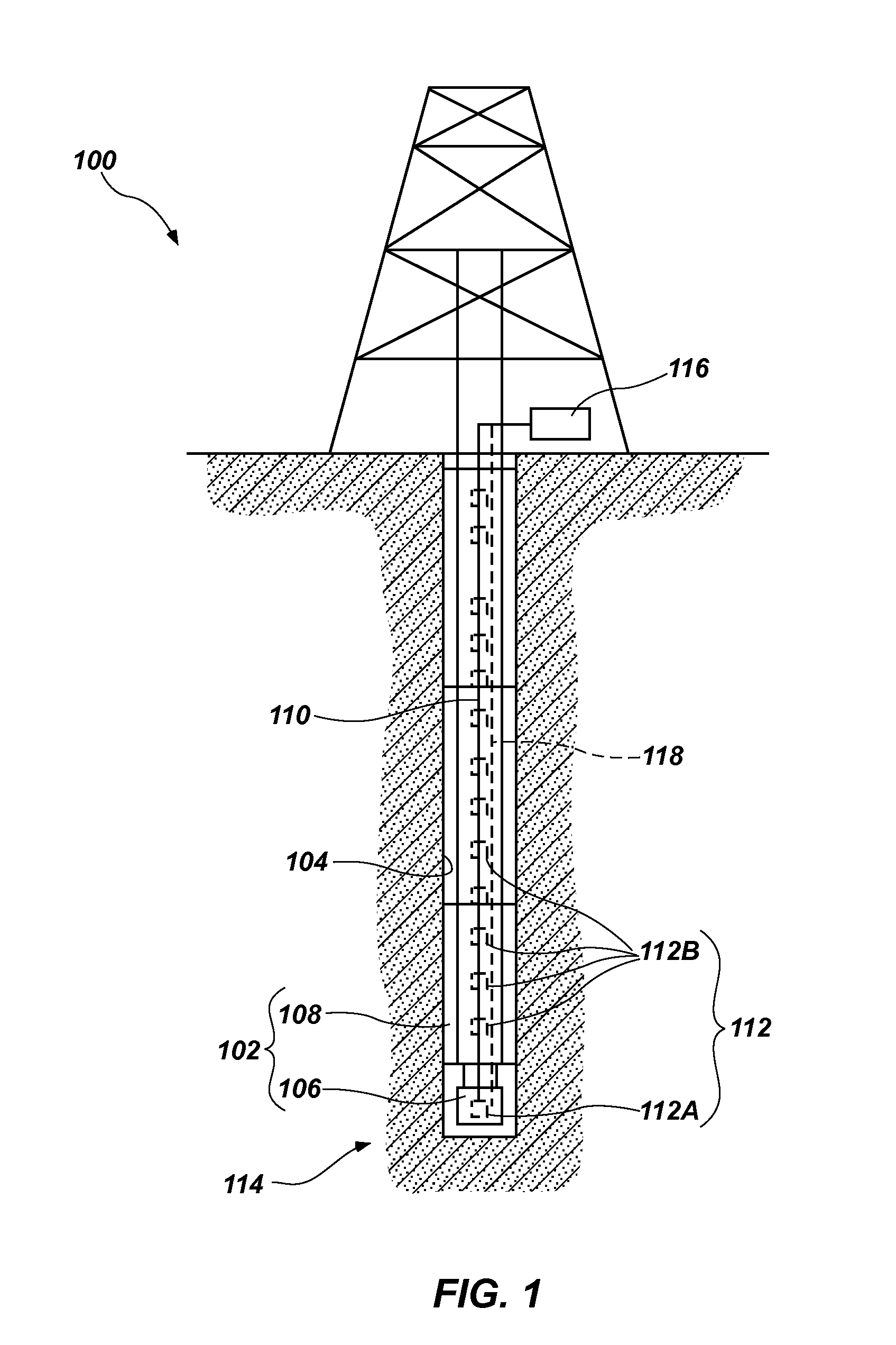
FIELD[0001]Embodiments of the present disclosure relate to systems and devices for sensing corrosion and deposition in equipment for the exploration and production of oil and gas, including, without limitation, corrosion of tools and tool components and deposition of scale on tools and tool components used in wellbores and surface equipment.BACKGROUND[0002]Tools and instruments used for oil and gas exploration and production are often exposed to corrosive conditions, such as high temperatures, high pressures, reactive chemicals, and abrasive materials. Therefore, these tools corrode and degrade during use. In addition, scale (i.e., debris and materials from the wellbore or from fluids therein) may be deposited on tools used for exploration and production of oil and gas, which may foul the operation of the tools and create a flow restriction. Fiber optic sensors have several advantages over electro-mechanical sensors: they exhibit greater resistance to aggressive environments, exhibi...

Claims


Application Information

Patent Timeline
Patent Type & Authority Applications(United States)
IPC IPC(8): G01N17/04G01V8/16G01B11/06
CPCG01N17/04G01B11/0675G01B11/14E21B47/00E21B47/123E21B47/135E21B47/006
Inventor CHILUKURI, ANUSHAMONTEIRO, OTHON R.
Owner BAKER HUGHES INC
Learn More