Safety gate with a rewindable, rlexible barrier

a safety gate and lock mechanism technology, applied in the direction of safety guards, sliding grilles, ways, etc., can solve the problems of not allowing air to flow back, time it takes to translate back into their locked positions, adds to time delay, etc., and achieves the effect of slowing down their movemen

Inactive Publication Date: 2015-12-31
SUMMER INFANT USA
View PDF3 Cites 5 Cited by
  • Summary
  • Abstract
  • Description
  • Claims
  • Application Information

AI Technical Summary

Benefits of technology

[0004]A retractable safety gate composed of a flexible barrier and a releasable locking mechanism is provided. The gate itself is composed of a flexible barrier sheet windably disposed about a substantially hollow spool and capable of extension from and retraction onto the spool. The winding spring is operatively connected to the bottom end of the spool. The winding spring applies continuous torque on the spool and is able to retract the barrier when in its extended position across a passageway. At the other, uppermost, end of the spool is a cap mounted on the spool in a sealed manner and comprising the locking mechanism. Two embodiments of the locking mechanism are provided. In the first embodiment, the interior of the cap is formed with interiorly disposed angular teeth that extend downward vertically and the top of the cap has an opening in which a lock release, in the form of a depressible button, is disposed. In the second embodiment, instead of a depressible button, a lever is operatively connected to a compression spring through a cam, both of which are is positioned within the cap.
[0005]In the first embodiment within the cap, a cylindrical spline lock is rotatably attached to the top of the spool. The spline lock is formed with an angular toothed surface disposed and arranged to engage and disengage with the cap teeth to prevent rotation in one rotational direction and permit rotation in the opposite rotational direction. A spline geometry is disposed within or atop the uppermost portion of the spool and is operatively connected with the spline lock to move the spline lock axially in relation to the spool with the application of pressure on the lock release. Time delay means comprising a compression spring is positioned within the cap and surrounding the spline lock and a one-way air check valve is mounted in the spline lock so that when the compression spring is compressed by a force imposed on the lock release, air is forced through the check valve and blocks airflow into the cap when the force on the lock release and compression spring is removed. In the second embodiment, the cylindrical spline lock is rotatably attached to the top of the spool and is formed with a circumferential toothed outer edge that engages and disengages with housing teeth mounted on a stationary bracket 38 and positioned within the cap. The spline geometry is disposed within or atop the uppermost portion of the spool and is operatively connected with the spline lock to allow the movement of the spline lock axially in relation to the spool. The spline lock is forced upward and away from the housing teeth by a compression spring mounted beneath it. A lever actuated cam mechanism is mounted above the spline lock and limits the motion on the spline lock. As the lever actuated cam mechanism rotates, it pushes the spline lock downward to engage the teeth to lock the spool. When the lever actuated cam mechanism is rotated in the opposite direction, it allows the spline lock to move upward, separating the housing teeth from the toothed outer edge of the spline lock and allowing the spool to rotate.
[0006]The mechanism is intended for use in a retractable safety gate, and a retractable safety gate is also provided. The gate includes two gateposts and a flexible barrier sheet that is extensible between the two gateposts and windably disposed about a substantially hollow spool. The gate includes the locking mechanism as defined above that is mounted on the uppermost portion of the spool in an engaged manner. The spool and locking mechanism are disposed within a housing that has a longitudinal slit for permitting extension and retraction of the barrier sheet within the housing and about the spool. The housing is slidably mountable on one of the gateposts. The extending edge of the barrier sheet is formed with an engagement head and the other gatepost is formed to removably receive the engagement head to temporarily position the barrier across the passageway. The spline lock teeth and the cap teeth are angularly formed such that they act in one direction only but allow for movement in the opposite direction. In the first embodiment, the teeth are kept engaged by means of the lock spring that continuously applies an upward force onto the spline lock, which restricts the spool from unwinding. In the second embodiment, the teeth are kept engaged by means of the lever, a cam mechanism, and the compression spring, which keeps the cam and spline lock in contact at all times.
[0007]In the first embodiment, when the lock release is pressed by the user, the compression spring compresses and pushes downward the spline lock, which disengages the spline lock teeth from the cap teeth. There is a body of air between the lock release and the cap that is a substantially sealed volume that compresses when the lock release is depressed. The volume of air is forced through the air check valve that is mounted in the spline lock. The air check valve allows the air to flow outside the sealed volume and displace the lock release rapidly but does not allow air to flow back in. When the force on the lock release is removed by the user, the compression spring pushes upward on the lock release and spline lock, creating a vacuum within the substantially sealed volume. Air flow into this vacuum is modulated by the dimensions of one or more spaces between the components in the housing and / or through the other components. This flow of air restricts the movement of the lock release and spline lock and slows their movement as they move back to their locked positions in which the angular teeth of the spline lock engage with the angular teeth of the cap interior. The amount of time it takes to translate back into their locked positions creates a time delay. Friction between the translating and fixed components of the mechanism adds to the time delay.

Problems solved by technology

The air check valve allows the air to flow outside the sealed volume and displace the lock release rapidly but does not allow air to flow back in.
The amount of time it takes to translate back into their locked positions creates a time delay.
Friction between the translating and fixed components of the mechanism adds to the time delay.

Method used


Image

  • Safety gate with a rewindable, rlexible barrier
  • Safety gate with a rewindable, rlexible barrier
  • Safety gate with a rewindable, rlexible barrier

Examples


first embodiment

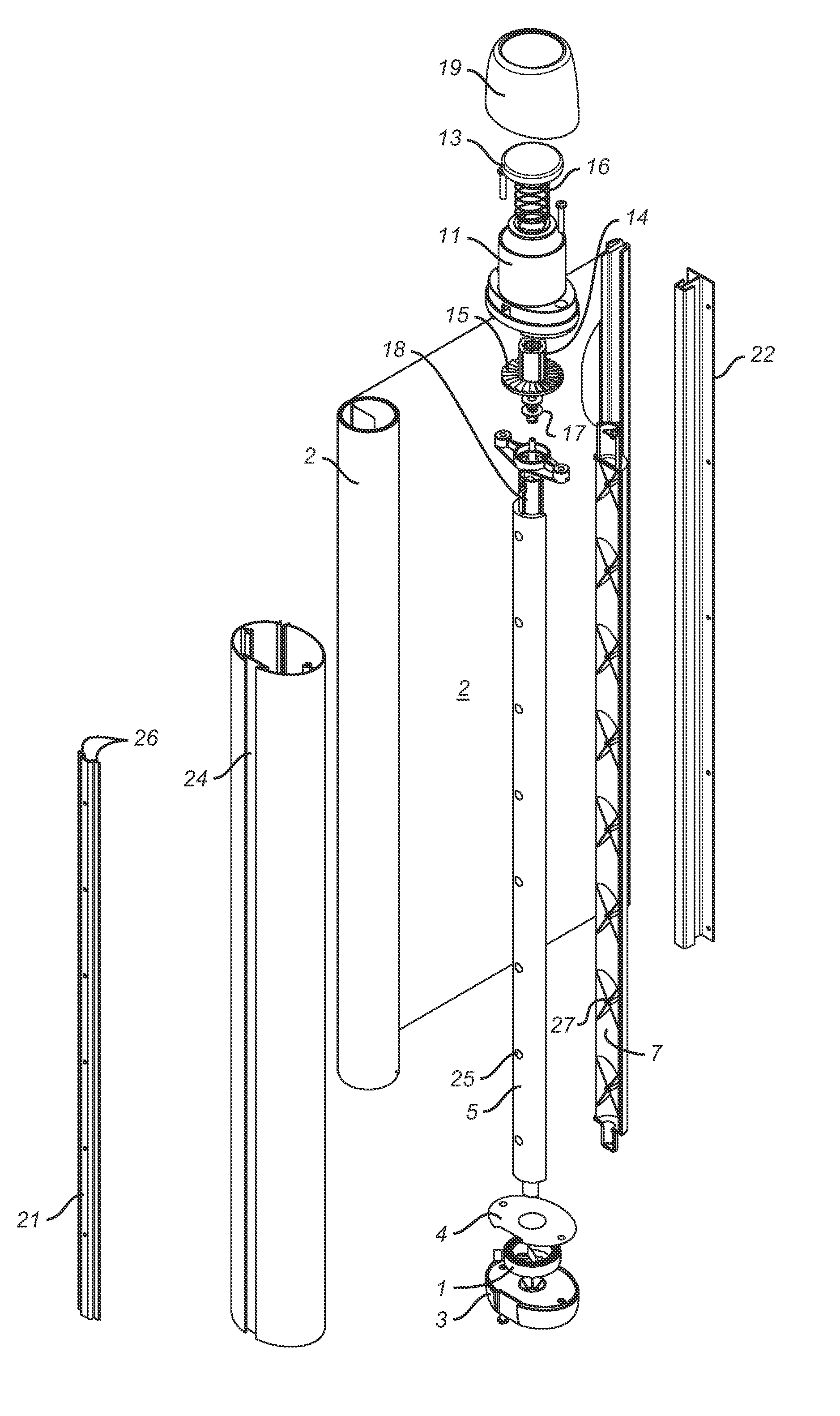
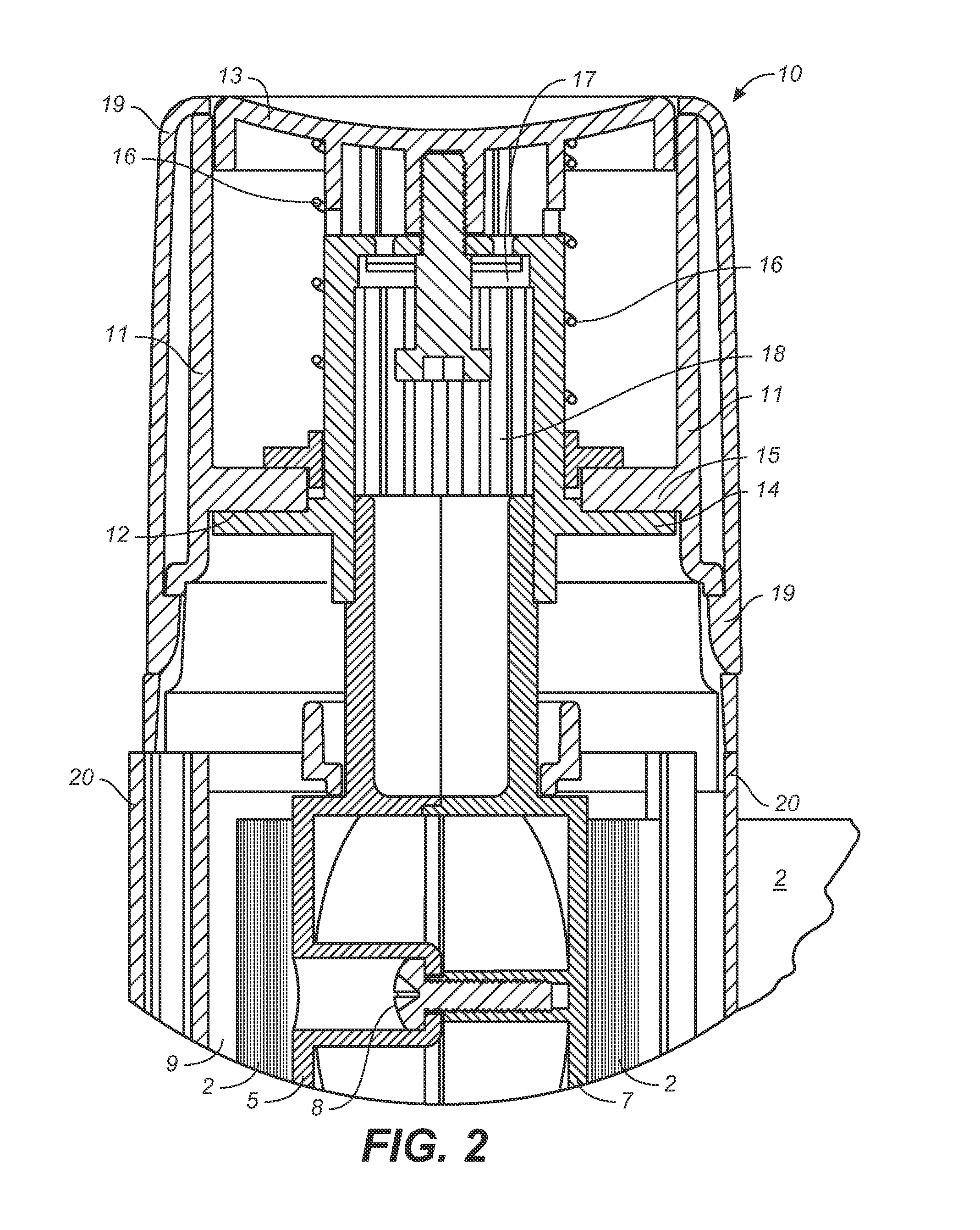
[0019]FIGS. 2 and 3 illustrate the rest of the releasable lock mechanism 10 of the invention. At the uppermost, end of the spool is a top cap, 11, mounted on the spool in a sealed manner. The interior of the top cap, 11, is formed with interiorly disposed angular cap teeth 12 that extend downward vertically and the top of the top cap has an opening in which a lock release, 13, in the form of a depressible button, is disposed.

[0020]Within the top cap 11, a cylindrical spline lock, 14, is rotatably attached to the top of the spool. The spline lock 14 is formed with an angular toothed surface, 15, disposed and arranged to engage and disengage with the interiorly disposed angular cap teeth 12 to prevent rotation in one rotational direction and permit rotation in the opposite rotational direction. A spline geometry, 18, is disposed within or mounted on the uppermost portion of the spool and is positioned within the spline lock and is operatively connected with it to move the spline lock ...

second embodiment

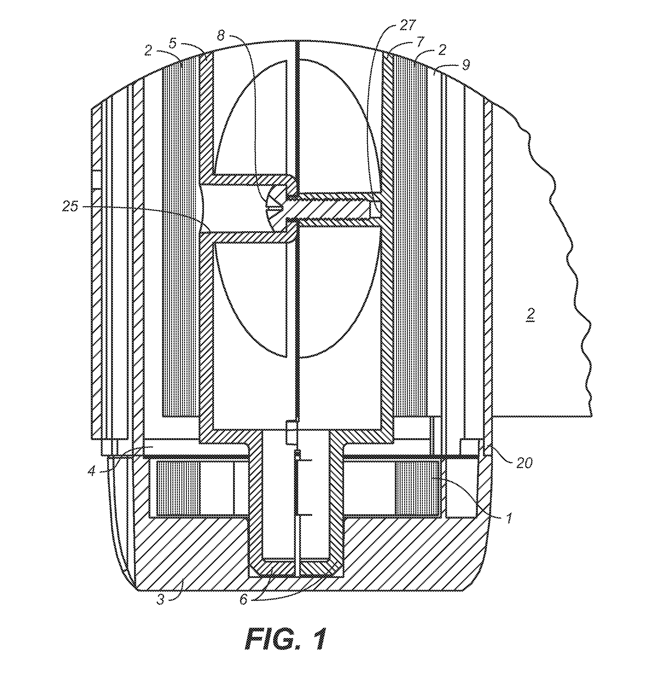
[0023]FIGS. 6 and 7 illustrate the releasable lock mechanism. Inside cap 11, cylindrical spline lock, 14, is rotatably attached to the top of spool halves 5 and 7. The spline lock, 14, is mounted on a spline geometry, 18, which is disposed within the uppermost portion of the spool and is operatively connected to it to allow the movement of the spline lock axially in relation to the spool. (The spline geometry has male and female portions, male portion 18 is shown in FIG. 6 and is mounted on the spool ends. Female portion 18 is formed as four integral, spaced-apart, inner indentations of the spline lock as can be seen in FIG. 7.) The spline lock, 14, is formed with a toothed outer edge, 30, disposed and arranged around the circumference of the spline lock. Also inside the cap is a stationary spline lock bracket, 34, that is mounted on cap 11. The bracket is formed with circumferential bracket teeth, 35, on the central and inner surface of bracket 34. Teeth 35 are able to engage with ...


PUM


Abstract

Provided is a retractable safety gate and locking mechanism for a retractable safety gate that employs a flexible barrier windable around a rotating spool, a lever or time release cap, a spline lock, meshing teeth, a spline geometry for extending and retracting the barrier.

Description

RELATED APPLICATIONS[0001]This application is a continuation-in-part of, and claims the benefit of, U.S. Ser. No. 13 / 961,183 filed Aug. 7, 2013.INVENTION FIELD[0002]The invention relates to safety gates and to lock release mechanisms for safety gates, more particularly to safety gates having flexible, retractable barriers.BACKGROUND[0003]Retractable safety gates composed of flexible barrier sheets and winding mechanisms are known. One example is disclosed in PCT patent publication WO94 / 00664, in which a roll of flexible sheet material is disposed in a housing that is vertically mounted to one side of a passageway. When the sheet material is extended across the passageway, it is received and releasably held by another housing mounted to the opposite side of the passageway. To accommodate passageways of varying widths, the barrier sheet will often be longer than the passageway it extends across. Consequently, a lock mechanism must be provided to prevent over-extension of the barrier o...

Claims


Application Information

Patent Timeline
Patent Type & Authority Applications(United States)
IPC IPC(8): E06B9/60E06B11/02E06B5/10E06B9/80
CPCE01F13/028E06B9/08E06B11/026E06B2009/002
Inventor HENDERSON, WILLIAM A.
Owner SUMMER INFANT USA
Why Eureka
Try Eureka