Vacuum cleaner tool

a vacuum cleaner and tool technology, applied in the direction of suction cleaners, cleaning equipment, suction nozzles, etc., can solve the problems of b>2/b> often contacting the cleaning surface of the nozzle, and achieve the effect of less likely to mark the cleaning surface, less friction, and smoother chang

Inactive Publication Date: 2015-12-31
DYSON TECH LTD
View PDF3 Cites 2 Cited by
  • Summary
  • Abstract
  • Description
  • Claims
  • Application Information

AI Technical Summary

Benefits of technology

[0006]The gap ensures that, as the tool is swept forwards over the cleaning surface, less dirt is pushed by the nozzle. Consequently, in contrast to the tool of FIGS. 1 and 2, the pickup performance of the tool is improved.
[0014]The bristle assembly may comprise a strip of bristles formed of carbon fibre. A strip of bristles has the advantage that no streaks of dirt are left behind as the tool is swept over the cleaning surface. Carbon fibre has at least two advantages. First, carbon fibre allows for relatively soft and fine bristles to be used, which help reduce marking of the cleaning surface. Second, carbon fibre has good anti-static properties, which means that the bristles can be swept over the cleaning surface without charging the surface. In contrast, nylon bristles tend to charge the cleaning surface and the resulting static then acts to attract dirt to the cleaning surface.

Problems solved by technology

A problem with the tool 1 is that, as the tool 1 is swept forwards, the leading edge of the nozzle 2 often contacts the cleaning surface.

Method used


Image

  • Vacuum cleaner tool
  • Vacuum cleaner tool
  • Vacuum cleaner tool

Examples


Embodiment Construction

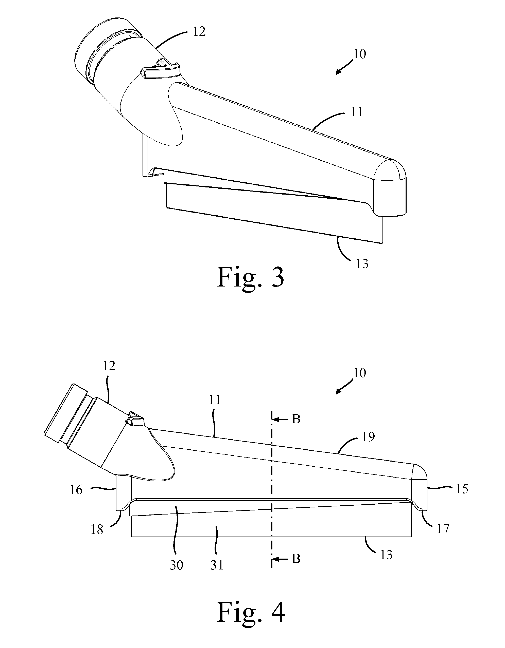
[0030]The vacuum cleaner tool 10 of FIGS. 3 to 8 comprises a nozzle 11, a connecting duct 12, and a bristle assembly 13.

[0031]The nozzle 11 is a relatively narrow structure, with the width of the nozzle 11 being much smaller than the length of the nozzle 11. The height of the nozzle 11 tapers (i.e. decreases gradually) from the rear 16 to the front 15 of the nozzle 11, the advantages of which are explained below. The nozzle 11 comprises a suction opening 20 that opens up into an internal cavity 21 within the nozzle 11. The suction opening 20 is located in the base of the nozzle 11 and extends centrally from the front 15 to the rear 16 of the nozzle 11. The suction opening 20 is delimited along its length by two edges 22, 23 of the nozzle 11. Each edge 22, 23 is raised relative to the lower ends 17, 18 of the front 15 and the rear 16 of the nozzle 11. Consequently, when the base of the nozzle 11 is brought into contact with a cleaning surface 40, a gap 25 is created between each of t...


PUM


Abstract

A tool for a vacuum cleaner that comprises a nozzle and a bristle assembly. A suction opening is provided in the base of the nozzle, which extends from a front to a rear of the nozzle. The bristle assembly is mounted within the nozzle and protrudes through the suction opening. The suction opening is delimited along its length by a leading edge and a trailing edge, and at least part of the leading edge is raised relative to a front end and a rear end of the nozzle. Consequently, when the tool is swept over a cleaning surface and the front end and the rear end of the nozzle contact the cleaning surface, a gap is created between the cleaning surface and the leading edge.

Description

REFERENCE TO RELATED APPLICATIONS[0001]This application is a national stage application under 35 USC 371 of International Application No. PCT / GB2014 / 050458, filed Feb. 17, 2014, which claims the priority of United Kingdom Application No. 1302907.9, filed Feb. 19, 2013, the entire contents of which are incorporated herein by reference.FIELD OF THE INVENTION[0002]The present invention relates to a tool for a vacuum cleaner.BACKGROUND OF THE INVENTION[0003]FIGS. 1 and 2 illustrate a known type of vacuum cleaner tool 1. The tool 1 comprises a nozzle 2 having an elongate suction opening 3, and a strip of the bristles 4 that protrude through the suction opening 3. The tool 1 is intended to be swept from side-to-side in directions normal to the suction opening 3. As the tool 1 is swept forwards, the bristles 4 bend backwards and contact the trailing edge of the nozzle 2. The suction opening 3 is therefore located in front of the bristles 4 irrespective of the direction of travel.[0004]A pr...

Claims


Application Information

Patent Timeline
Patent Type & Authority Applications(United States)
IPC IPC(8): A47L9/06
CPCA47L9/0606A47L9/062A47L9/066A47L9/0613
Inventor COLE, SAMUEL STEVENMCVEIGH, BRIANGAMMACK, PETER DAVIDDYSON, JAMES
Owner DYSON TECH LTD
Why Eureka
Try Eureka