
Header with center part and side parts adjustable relative to the center part

a technology of center part and side parts, applied in headers, agriculture, agricultural tools and machines, etc., can solve the problems of unsusceptible support of two side parts, achieve the effect of reducing the leverage force that is acting on the feed channel and the frame of the combine harvester, and achieving faster and easier

Active Publication Date: 2015-12-31
CARL GERINGHOFF GMBH & CO KG
View PDF3 Cites 12 Cited by
  • Summary
  • Abstract
  • Description
  • Claims
  • Application Information

AI Technical Summary

Benefits of technology

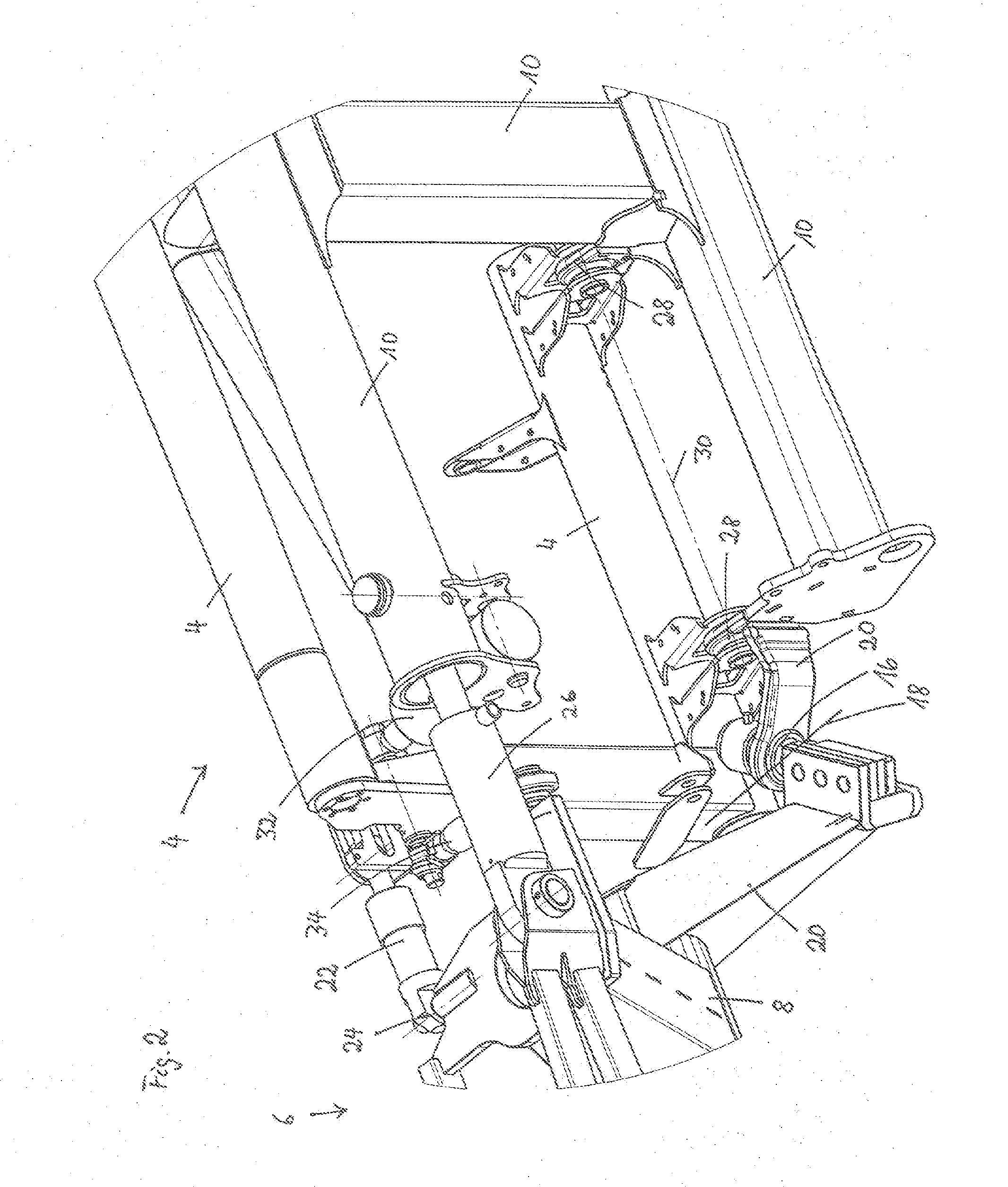
The invention relates to a combine harvester with a pivotable lateral frame and a ball joint that connects the frame to the feed channel. The ball joint is positioned at the lower half of the feed channel, which keeps the center of gravity low and prevents changes in the belt length. A motorized guide arm is connected to the ball joint and can adjust the position of the frame. This allows for continuous ground adjustment as the combine harvester moves forward. The invention provides an automation solution for continuous ground adjustment and remote operation from the driver's cabin. The use of a hydraulic cylinder as a servomotor enables high adjusting forces and precise adjustability of the pivot position. The lateral frame is supported against the center part or the attachment frame with a force store, which can be a mechanical spring or a pneumatic or hydraulic buffering action. The positioning angle of the center part can be adjusted by the motorized guide arm, and the adjustment is transmitted to the lateral frames through coupling rods. The use of a hinge with a hinge axis that intersects the ball joints allows for easy adjustment of the positioning angle. The motorized guide arm is designed to be lightweight and compact, reducing the total weight and construction expenditure of the header.

Problems solved by technology

The ball joints on which the two side parts are supported are unsusceptible to soiling, they are low-maintenance, and can absorb high loads.

Method used


Image

  • Header with center part and side parts adjustable relative to the center part
  • Header with center part and side parts adjustable relative to the center part
  • Header with center part and side parts adjustable relative to the center part

Examples


Embodiment Construction

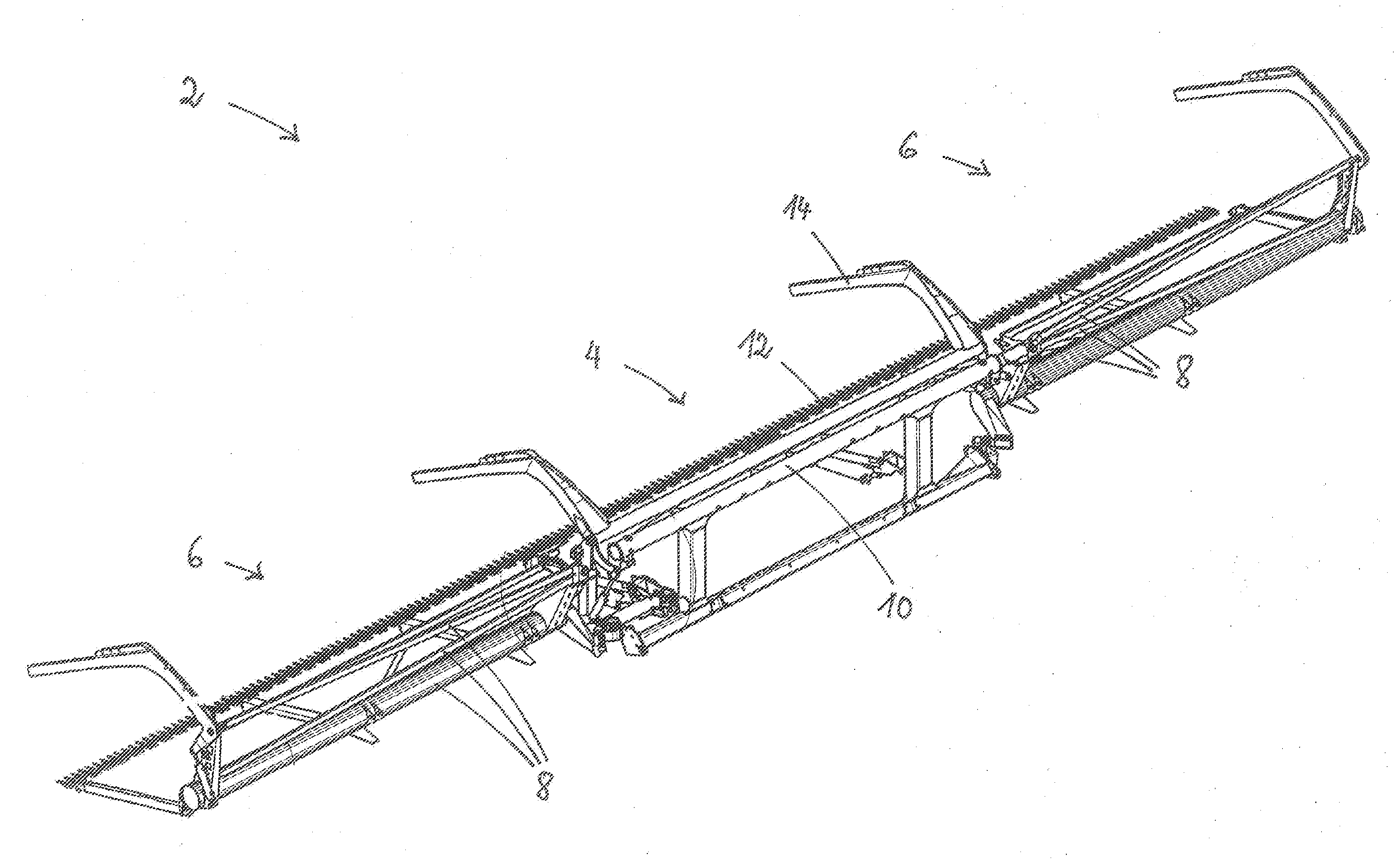
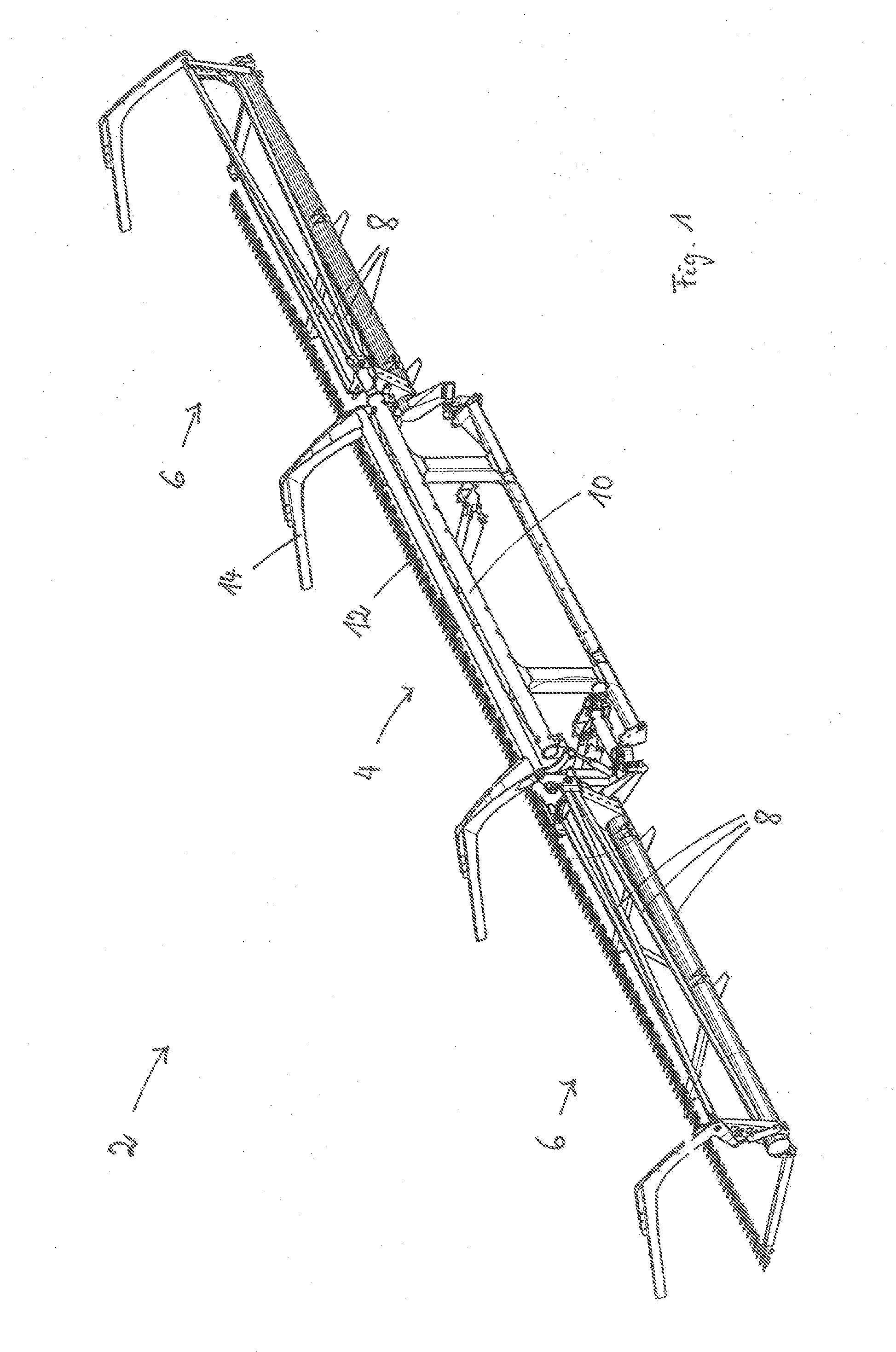
[0021]In FIG. 1, a header 2, viewed in the travel direction of a combine harvester, is shown in a view at a slant from above. The header 2 is comprised in the embodiment of a center part 2 having at both sides a side part 6 each. Each side part 6 comprises a lateral frame 8 which is connected to the attachment frame 10. The attachment frame 10 is designed such that it surrounds the feed channel of a combine harvester, not shown in detail in the drawing, when the header is attached to the combine harvester. By means of the attachment frame 10, the header 2 is thus connected to the feed channel of the combine harvester which supports the header 2 during harvest. At the front end of the header 2, there is a cutter bar 12 with which grain to be harvested is cut.

[0022]For reasons of simplification, in FIG. 1 the conveying elements with which the cut crop is transported toward the center of the header and from there is transferred to the feed channel of the combine harvester are not illus...


PUM


Abstract

A header of a combine harvester has a center part connected by an attachment frame to the combine feed channel. A first side part with first lateral frame and a second side part with second lateral frame are adjustable for changing their position relative to the center part. The first and second lateral frames are connected by a first ball joint and a second ball joint to the attachment frame, respectively so that the weight of the first and second lateral frames is supported by the first and second ball joints on the attachment frame. The first and second ball joints form first and second pivot axes. An end of the first lateral frame facing away from the center part is pivotable about the first pivot axis. An end of the second lateral frame facing away from the center part is pivotable about the second pivot axis.

Description

BACKGROUND OF THE INVENTION[0001]The present invention concerns a multi-part header for attachment to a combine harvester, comprising a center part that is connectable by means of an attachment frame to the feed channel of a combine harvester and at least two side parts each to a corresponding lateral frame whose relative position to the center part is adjustable.[0002]U.S. Pat. No. 4,956,966 discloses a header of the aforementioned kind that is connectable by means of an attachment frame to the feed channel of a combine harvester. The attachment frame is height-adjustably connected to the feed channel in order to be able to guide the header upon forward travel into a grain field at an appropriate spacing to the ground. The attachment frame is additionally pivotable about an axis that extends parallel to the forward travel direction of the combine harvester in order to be able to adjust, in transverse direction, the position of the header relative to the ground contour that is chang...

Claims


Application Information

Patent Timeline
IPC IPC(8): A01D34/28A01D47/00A01D67/00A01D41/14
CPCA01D41/16A01D41/06
Inventor SCHULZE RÜCKAMP, JAN BERNDSUDHUES, STEFFENTIESSEN, REIMERPOKRIEFKE, MICHAELSONNEN, ROBERTSURMANN, KLEMENS
Owner CARL GERINGHOFF GMBH & CO KG
Learn More