Cooking Appliance

a technology for cooking appliances and cooking vessels, applied in the field of cooking, can solve the problems of food absorbing too much unhealthy fat, fat giving food an undesirable taste, excess fumes, etc., and achieve the effect of ensuring the stability of the appliance and maintaining the low centre of gravity of the applian

Inactive Publication Date: 2015-12-24
SUNBEAN PROD INC
View PDF7 Cites 14 Cited by
  • Summary
  • Abstract
  • Description
  • Claims
  • Application Information

AI Technical Summary

Benefits of technology

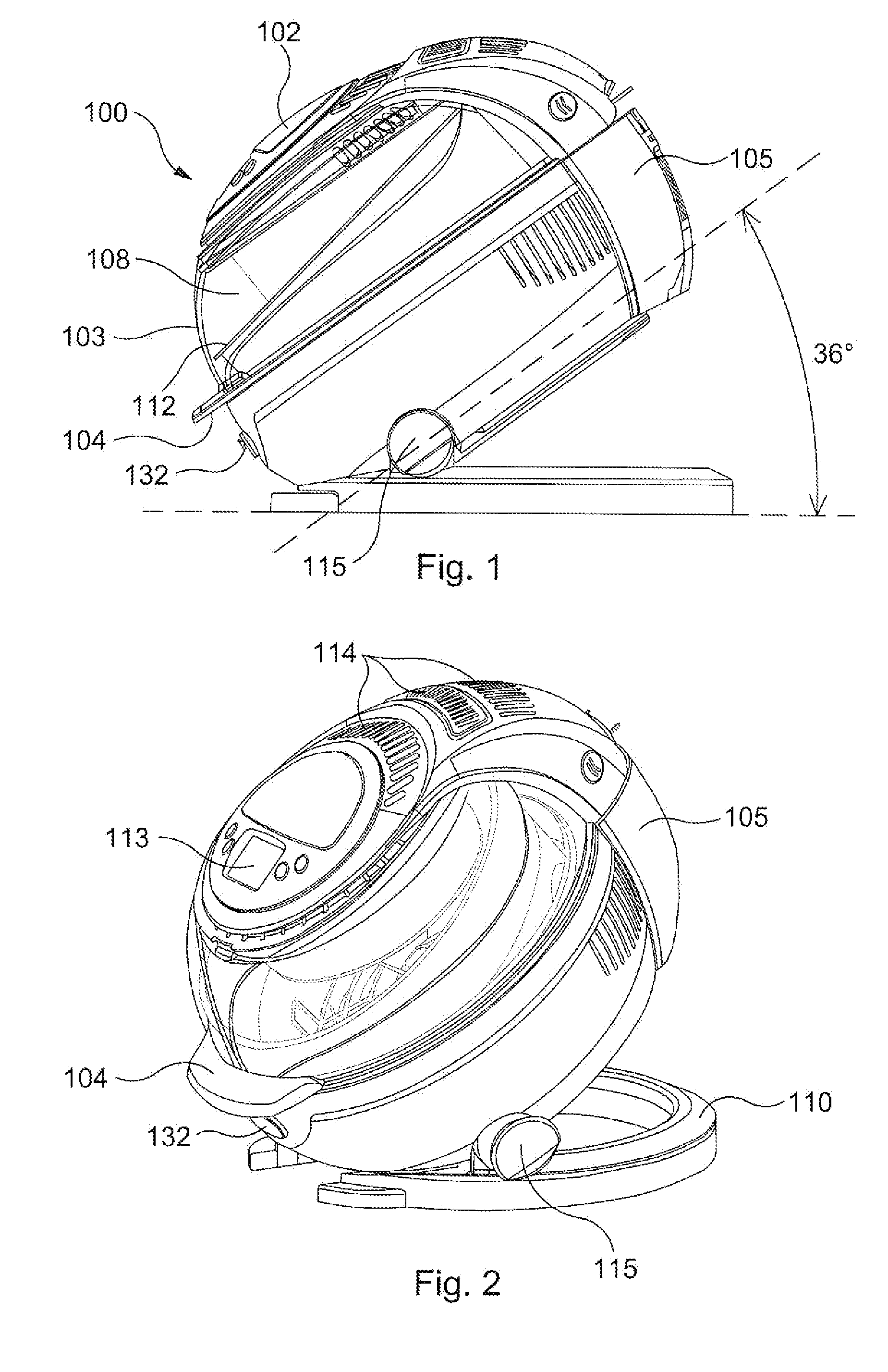
[0007]The housing may be pivotally connected to the base at or towards a lowermost region of the housing, when in use. This aids stability of the appliance when the housing is angled with respect to the base and ensures that the centre of gravity of the appliance remains low. In particular embodiments, the housing may be pivotally connected to the base at a height that is below the height of the cooking bowl (e.g. below the bottom wall), when the housing is in the horizontal position. In addition, the housing may be pivotally connected to the base at or towards a front region of the housing, when in use. This allows the base to have a height which is lower than would be required to accommodate the tilt of the housing if the pivot was in the centre of the appliance and also ensures that the control panel is angled towards the user, when in use. In particular embodiments, the housing may be pivotally connected to the base approximately half-way between the centre and the front of the housing.

Problems solved by technology

However, there are drawbacks to cooking food in this manner including the food absorbing too much unhealthy fat, the fat giving the food an undesirable taste, excess fumes, and costly amounts of fat or cooking oil must be used.

Method used


Image

  • Cooking Appliance
  • Cooking Appliance
  • Cooking Appliance

Examples


Embodiment Construction

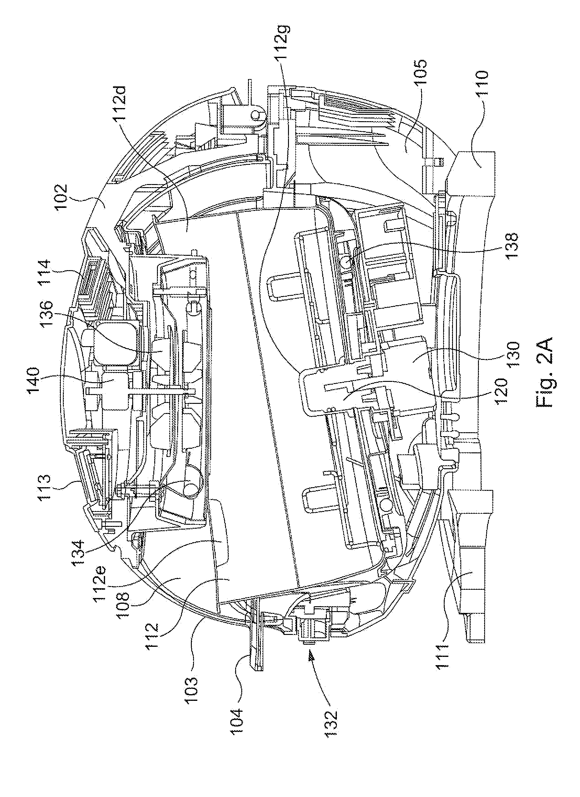
[0021]Referring now to the drawing figures in which like reference designators refer to like elements, there is illustrated in FIGS. 1-2A an embodiment of a cooking appliance 100 similar to a cooking appliance disclosed in Chinese Utility Model Patent Application No. ZL 201120326254.4 filed on Sep. 1, 2011 (Chinese Publication No. 202234714 published May 30, 2012), which is incorporated by reference as if fully rewritten herein. The utility model is directed towards a rotary multifunctional cooker comprising a cooker body, cover and heater. The body is provided with an inclined rotary basin and heat flow ducting is provided to circulate heated air over the food in the basin. The basin is inclined at a fixed angle of greater than 15 degrees to the horizontal and a blocking element is provided in a sidewall of the basin. However, the angle of tilt of the basin is not adjustable.

[0022]The cooking appliance 100, according to an embodiment of the present invention, includes a housing 105...


PUM


Abstract

A cooking appliance comprises a base, a housing pivotally mounted to the base and a lid pivotally attached to the housing forming a cooking chamber when the lid is in the dosed position. A heating means and a blower means are provided for generating a cooking airflow, A latching pivoting means pivotally connects the housing to the base and is configured to allow the housing to be pivoted from a locked horizontal position to one or more angular positions offset from the horizontal position and to releasably lock the housing in said angular position. A cooking bowl is removably mounted in the housing and is rotated during cooking by a drive motor, wherein food contents are placed into the cooking bowl and the cooking airflow cooks the food contents during cooking. A projection formed partially in a bottom wall and a sidewall of the cooking bowl is configured to stir the food contents in the cooking bowl when the cooking bowl is rotated during cooking.

Description

FIELD OF THE INVENTION[0001]The invention relates to cooking, and more particularly, to a cooking appliance designed for frying food.BACKGROUND OF THE INVENTION[0002]It is known in the art to cook food with a cooking appliance using fat or cooking oil. Many of such cooking appliances immerse the food to be cooked in a vat of heated oil for a period of time until the food is cooked to a desired level of doneness. However, there are drawbacks to cooking food in this manner including the food absorbing too much unhealthy fat, the fat giving the food an undesirable taste, excess fumes, and costly amounts of fat or cooking oil must be used. As such, there is a need for a cooking appliance that can cook different foods with various amounts of fat or cooking oil, in particular, where the amount of fat or cooking oil is the minimal amount required to coat the food with fat or oil and fry the food.SUMMARY OF THE INVENTION[0003]The invention is as defined in claim 1 with optional features pre...

Claims


Application Information

Patent Timeline
Patent Type & Authority Applications(United States)
IPC IPC(8): A47J27/00A47J37/10
CPCA47J37/10A47J27/002A47J36/00A47J36/34A47J43/046A47J27/00A47J27/004
Inventor FAREHAM, PETERGORDON, STEWART
Owner SUNBEAN PROD INC
Why Eureka
Try Eureka