A remote controllable switch operating device
a technology of operating device and switch, which is applied in the direction of remote-control toys, contact mechanisms, coupling device connections, etc., can solve the problems of not allowing immediate control, requiring specialist parts, and requiring light fitting replacement, etc., to reduce the requirement for batteries.
- Summary
- Abstract
- Description
- Claims
- Application Information
AI Technical Summary
Benefits of technology
Problems solved by technology
Method used
Image
Examples
first embodiment
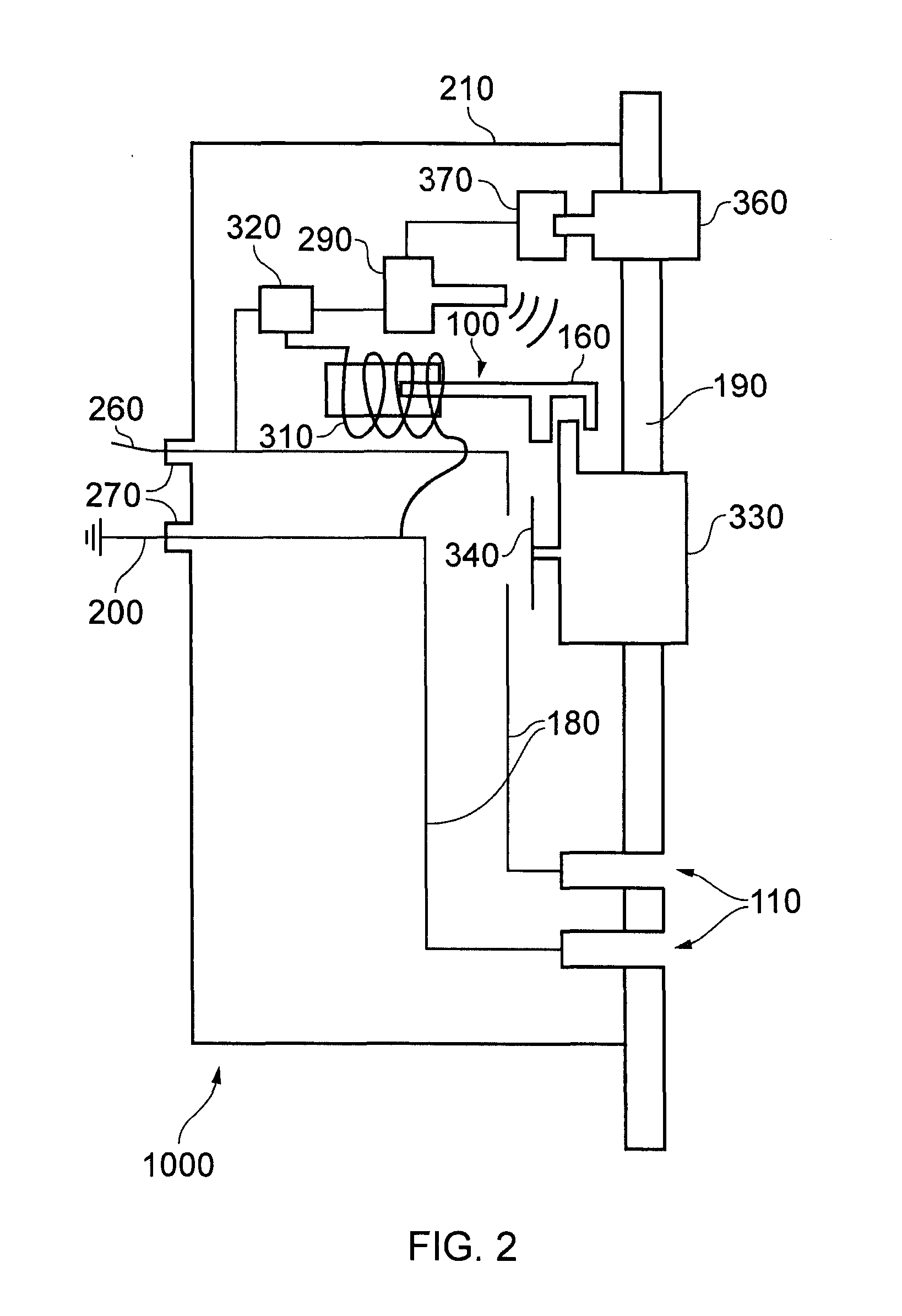
[0068]FIG. 2 shows a schematic of the operating device. A switch 330 protrudes through a fascia 190. The switch 330 is exposed to a user who can see and touch the switch 330 where it protrudes through the fascia 190.
[0069]The user displaces the switch 330 to move electrical contacts 340. By bringing the contacts 340 into contact with the terminals of an electrical circuit 180, the electrical circuit 180 is closed. The user displaces the switch 330 to open and close the circuit 180.
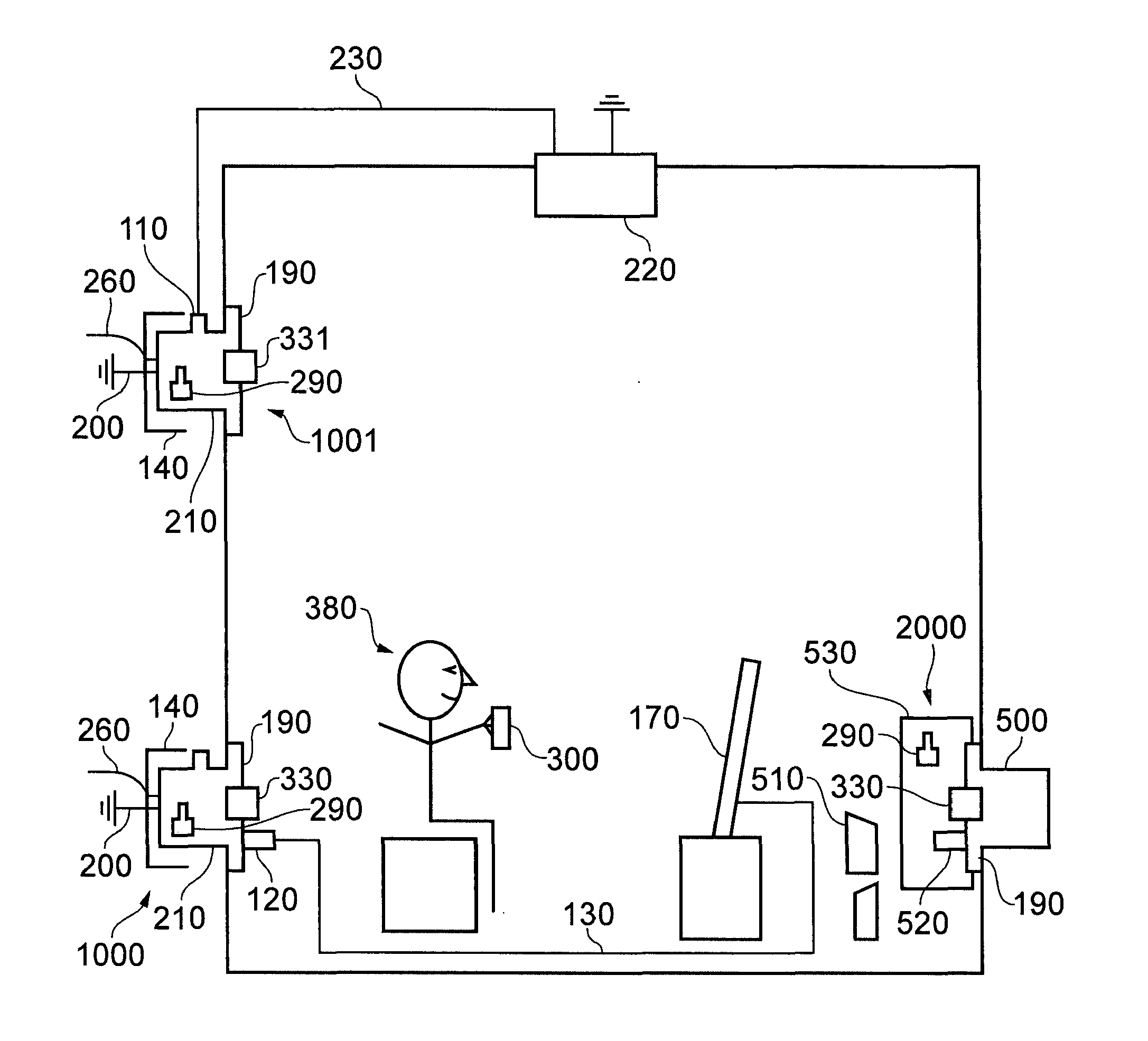
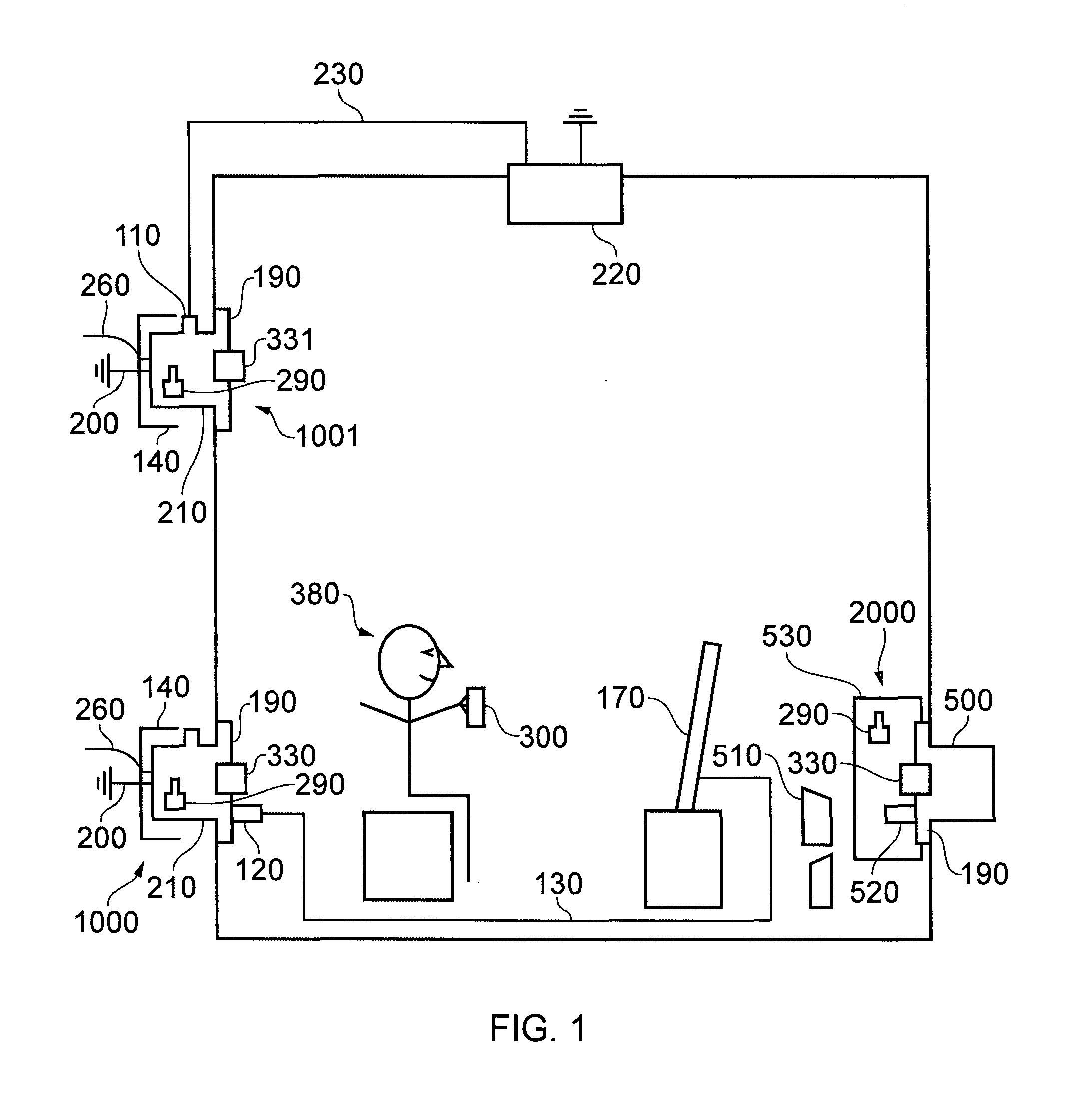
[0070]As shown in FIG. 2, the electrical circuit 180 connects a power supply connector 260 to an electrical appliance connector 110. The appliance connector 110 is a socket suitable for receiving plug 120 as the one illustrated in FIG. 1 at the end of the television appliance wire 130. The power supply connector is adapted to connect to a power cable 260. The power cable 260 is part of mains electrical wiring in a building. A terminal of the socket 110 is also connected directly by the circuit 180 to a gro...
second embodiment
[0093]FIG. 3 shows a schematic view of the remote controllable switch operating device 2000.
[0094]FIG. 4 shows a first example of the second embodiment of the operating device 2000 attached to a fascia of a switched interface 500. The switched interface 500 comprises a switch 330 which turns off and on electrical power to an appliance connector 110. Generally the appliance connector is a plug socket as shown in FIGS. 4 and 6.
[0095]Homes and offices are typically built with switch interfaces 500 which comprise a manually operable switch 330 to turn on and off electricity to a socket 110 in the interface or to turn on and off electricity to an appliance connector 110 that is connected to a light wire 230.
[0096]The second embodiment of the operating device 2000 is an external embodiment because it clamped the exterior of a switch interface 500. The second embodiment of the invention 2000 is arranged to clamp onto the fascia 190 of the switch interface 500.
[0097]In one example of the se...
PUM
 Abstract
Description
Claims
Application Information
 - R&D
- Intellectual Property
- Life Sciences
- Materials
- Tech Scout
- Unparalleled Data Quality
- Higher Quality Content
- 60% Fewer Hallucinations
Browse by: Latest US Patents, China's latest patents, Technical Efficacy Thesaurus, Application Domain, Technology Topic, Popular Technical Reports.
© 2025 PatSnap. All rights reserved.Legal|Privacy policy|Modern Slavery Act Transparency Statement|Sitemap|About US| Contact US: help@patsnap.com


