
Touch display device and touch substrate

Inactive Publication Date: 2015-12-17
INNOLUX CORP
View PDF4 Cites 10 Cited by
  • Summary
  • Abstract
  • Description
  • Claims
  • Application Information

AI Technical Summary

Benefits of technology

The invention aims to provide a touch display device and touch substrate that balance visibility and RC loading, and achieve better impedance matching. This is achieved through the design of different widths of bridge units on the first touch patterns, which help to balance the problems in the touch display and touch substrate. For example, the bridge unit has two first portions, a second portion, and two third portions, where the second width of the second portion is smaller to increase visibility, and the first width of the first portion is larger to decrease RC loading. Additionally, the connection width between the third portion and the first portion is greater than the connection width between the third portion and the second portion to achieve better impedance matching.

Problems solved by technology

However, because the metal layer is typically made of an opaque material, the visibility of the touch display device is affected.

Method used


Image

  • Touch display device and touch substrate
  • Touch display device and touch substrate
  • Touch display device and touch substrate

Examples


Embodiment Construction

[0031]The embodiments of the invention will be apparent from the following detailed description, which proceeds with reference to the accompanying drawings, wherein the same references relate to the same elements.

[0032]The present invention will be apparent from the following detailed description, which proceeds with reference to the accompanying drawings, wherein the same references relate to the same elements. All drawings of the embodiments of the invention are only for the illustrative purpose only, and do not intend to represent the true size and scale.

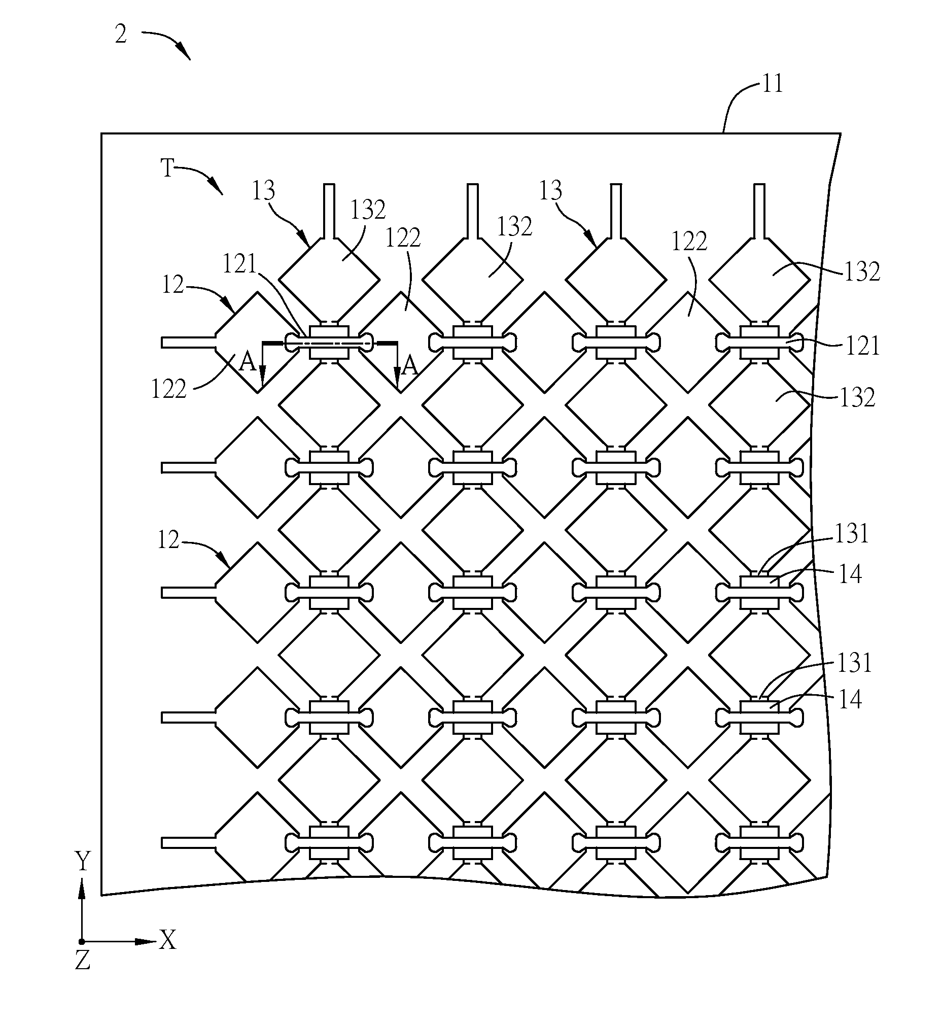
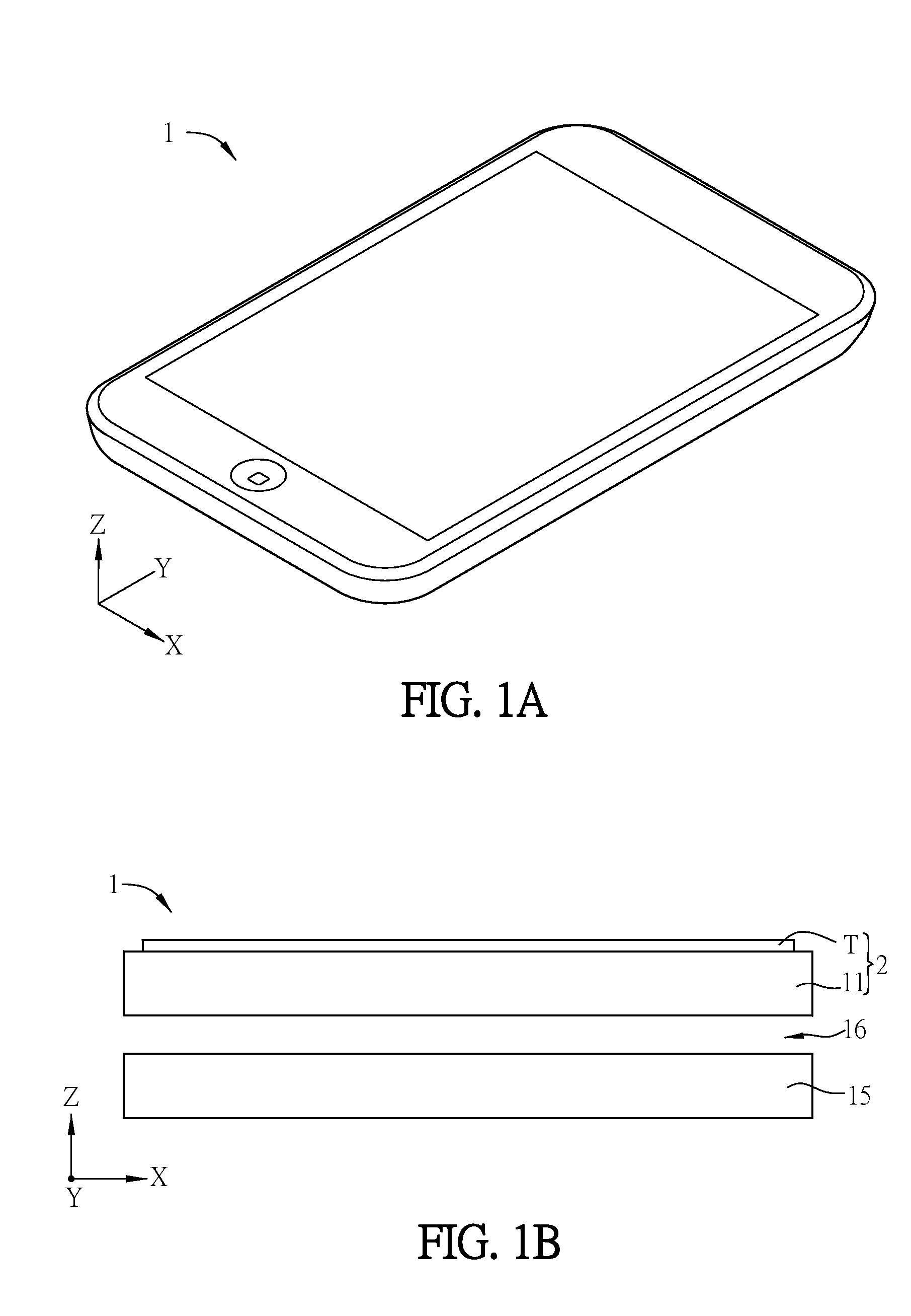
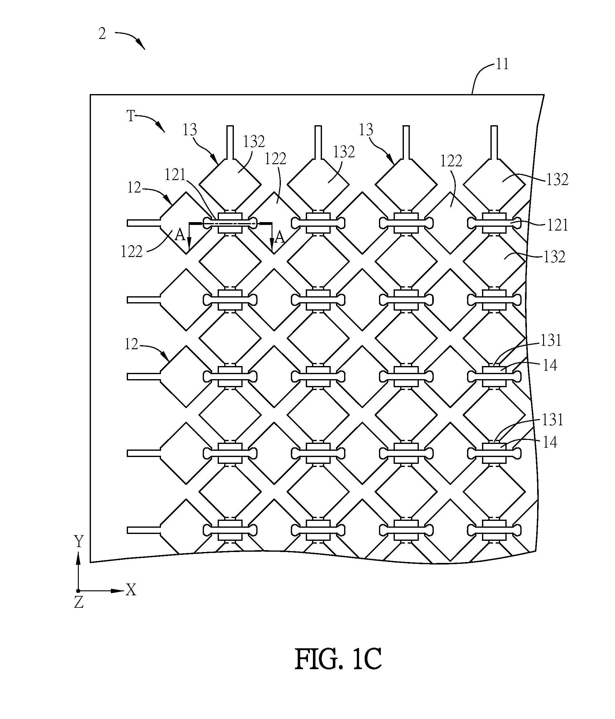
[0033]FIG. 1A is a schematic view showing a touch display device 1 according to a preferred embodiment of the invention. FIG. 1B is a schematically cross-sectional view showing the touch display device 1. FIG. 1C is a schematic top view showing a touch substrate 2 of FIG. 1B. FIG. 1D is a schematically cross-sectional view taken along a straight line A-A in the touch substrate 2 of FIG. 1C. FIG. 1E is a schematic top view of FIG....


PUM


Abstract

First touch patterns of a touch display device are disposed on a first substrate, and have bridge units and first electrode portions. The first electrode portions are disposed spaced from each other. The bridge units are connected with adjacent two of the first electrode portions. A second substrate is disposed opposite to the first substrate. A liquid crystal layer is disposed between the first substrate and the second substrate. One of the bridge units has two first portions, a second portion and two third portions. The first portions are located on the first electrode portions, and directly contact with the first electrode portions. The third portions are located on two of the first portions, and the second portion is located between two of the third portions. The first portion has a first width, and the second portion has a second width smaller than the first width.

Description

CROSS REFERENCE TO RELATED APPLICATIONS[0001]This Non-provisional application claims priority under 35 U.S.C. §119(a) on Patent Application No(s). 103120195 filed in Taiwan, Republic of China on Jun. 11, 2014, the entire contents of which are hereby incorporated by reference.BACKGROUND[0002]1. Technical Field[0003]The invention relates to a touch display device and a touch substrate.[0004]2. Related Art[0005]With the advancing technology, the touch technology has been widely applied to various electronic products. For the touch display device, the user can execute various functions by touching the touch display device, so that the operation complexity of the user can be simplified, and the touch display device becomes more and more popular.[0006]The touch display device may be typically an out-cell touch device or an on-cell touch device. In the aspect of the out-cell touch device, a touch sensing circuit is formed on a substrate, which is then combined with a display panel to form ...

Claims


Application Information

Patent Timeline
IPC IPC(8): G06F1/16G02F1/1333G06F3/041
CPCG06F1/16G06F2203/04111G02F1/13338G06F3/0412G06F3/047G06F3/0446G06F3/0445
Inventor CHEN, CHIH-CHANGHSU, WEI-TINGCHEN, YANG-CHENCHANG, CHIA-HSIUNG
Owner INNOLUX CORP
Learn More