Seal member and front fork provided with seal member

a technology of seal member and front fork, which is applied in the direction of shock absorbers, steering devices, cycle equipments, etc., can solve the problems of reducing the conformity with the inner tube, increasing the cost, and recurvation, so as to increase the thickness of the distal end, reduce the fastening force applied by the garter spring, and increase the thickness

Inactive Publication Date: 2015-12-17
KYB CORP
View PDF4 Cites 10 Cited by
  • Summary
  • Abstract
  • Description
  • Claims
  • Application Information

AI Technical Summary

Benefits of technology

[0009]However, the use of the garter spring leads to a cost increase. Also, the garter spring is a coil spring formed into an annular shape by connecting both ends thereof, the coil spring being a wire wound into a spiral shape. Hence, foreign substances are easily accumulated inside the garter spring. If the inside of the garter spring is filled with foreign substances, a fastening force applied by the garter spring decreases. Furthermore, a portion to which the garter spring is attached corresponds to the distal end portion of the dust lip, and it is necessary to increase the thickness of the distal end of the dust lip when the garter spring is attached. Therefore, if the distal end of the dust lip is oriented upward, foreign substances easily pile up on the distal end portion of the dust lip.
[0010]It is an object of the present invention to provide a seal member capable of suppressing a decrease in conformity with a shaft member such as an inner tube and recurvation even if a garter spring is not attached to a dust lip, and to provide a front fork provided with this seal member.

Problems solved by technology

Therefore, if the dust lip hardens due to deterioration, there is a possibility that the conformity with the inner tube decreases.
In this case, there is a possibility that recurvation occurs.
However, the use of the garter spring leads to a cost increase.
Hence, foreign substances are easily accumulated inside the garter spring.
Therefore, if the distal end of the dust lip is oriented upward, foreign substances easily pile up on the distal end portion of the dust lip.

Method used


Image

  • Seal member and front fork provided with seal member
  • Seal member and front fork provided with seal member
  • Seal member and front fork provided with seal member

Examples


first embodiment

[0017]First, a description is given of a

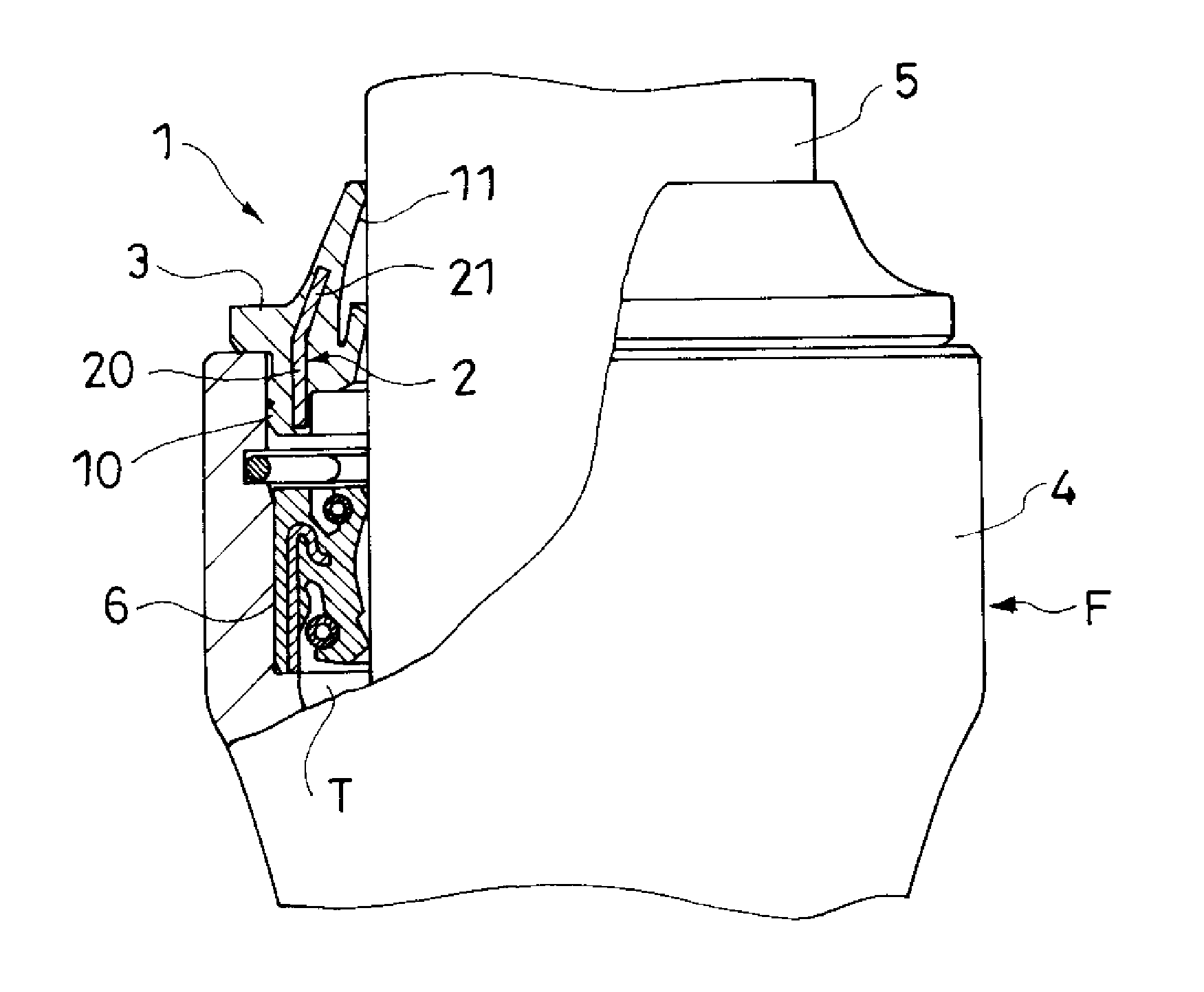
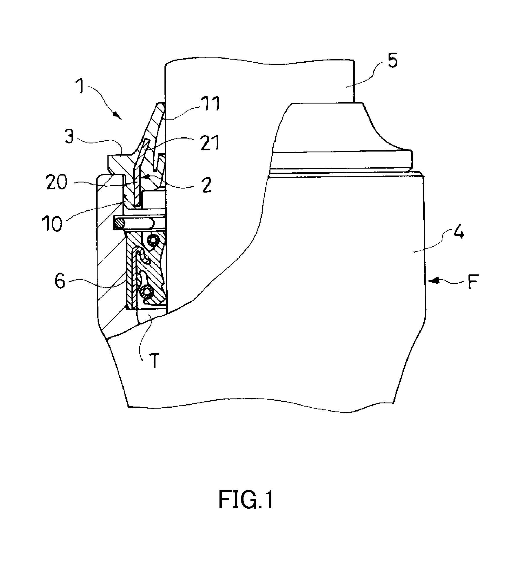
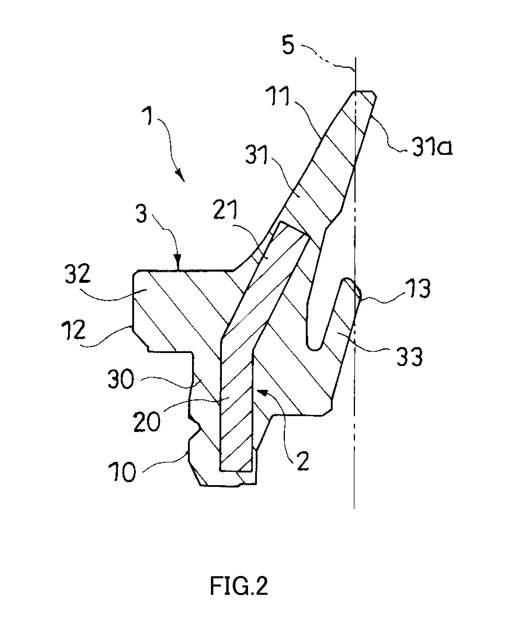
[0018]As shown in FIG. 1, a seal member 1 is formed of a metal insert 2 and an elastic body 3 which covers the metal insert 2. The seal member 1 seals a gap between an outer tube (tubular member) 4 and an inner tube (shaft member) 5 which is axially movably inserted into the outer tube 4. The seal member 1 includes an annular fitting part 10 and an annular dust lip 11. The fitting part 10 fits on an inner circumference of the outer tube 4. The dust lip 11 extends from the fitting part 10 toward a side opposite from the outer tube 4 (a side opposite from the tubular member) such that an inner circumference of the dust lip 11 gradually decreases in diameter, and a distal end portion of the dust lip 11 slides on an outer circumferential surface of the inner tube 5.

[0019]The metal insert 2 includes a reinforcing ring 20 and a reinforcing extension piece 21. The reinforcing ring 20 stands along the inner circumference of the outer tube (tubular mem...

second embodiment

[0042]A second embodiment will now be described.

[0043]As shown in FIG. 3, similarly to the seal member 1 according to the first embodiment, a seal member 7 is used in a front fork and serves as a dust seal which seals the gap between an outer tube 4 and an inner tube 5. Similarly to the seal member 1 according to the first embodiment, the seal member 7 is formed by insert molding, and is made by covering a metal insert 8, which is made of metal, with an elastic body 9 such as rubber. The metal insert 8 serves as a metal core for reinforcing the elastic body 9 which practically functions as a seal.

[0044]In a case where the seal member 7 is mounted on the outer tube 4, the metal insert 8 is made up of a reinforcing ring 80, an annular reinforcing extension piece 81, and a reinforcing flange piece 82 having a shape of an annular plate. The reinforcing ring 80 stands along an inner circumference of the outer tube 4. The reinforcing extension piece 81 is continuous with an end portion of...


PUM


Abstract

A seal member includes an annular fitting part and an annular dust lip. The fitting part fits on an inner circumference of a tubular member. The dust lip extends from the fitting part toward a side opposite from the tubular member such that a diameter of an inner circumference of the dust lip gradually decreases, and a distal end portion of the dust lip slides on an outer circumferential surface of a shaft member. A metal insert includes a reinforcing ring and a reinforcing extension piece. The reinforcing ring stands along the inner circumference of the tubular member. The reinforcing extension piece extends from the reinforcing ring toward a side opposite from the tubular member, and inclines such that a distal end of the reinforcing extension piece approaches the shaft member. The reinforcing ring is arranged in the fitting part, whereas the reinforcing extension piece is arranged in the dust lip.

Description

TECHNICAL FIELD[0001]The present invention relates to a seal member and a front fork provided with the seal member.BACKGROUND ART[0002]A shock absorber, a cylinder device, and the like include a tubular member such as a cylinder, and a shaft member such as a piston rod. The shock absorber generates a damping force using a working fluid such as a working oil. The cylinder device drives a target object by the working fluid. The working fluid is housed in the tubular member. The shaft member is axially movably inserted into the tubular member. The shock absorber and the cylinder device are extendable and compressible due to relative movements between the tubular member and the shaft member. A seal member is provided between the tubular member and the shaft member. The seal member prevents the working fluid from leaking from the tubular member.[0003]A shock absorber for a front fork which suspends a front wheel in a straddled vehicle such as a motorcycle includes a shock absorber main b...

Claims


Application Information

Patent Timeline
Patent Type & Authority Applications(United States)
IPC IPC(8): F16J15/32B62K21/02F16F9/36
CPCF16J15/3216F16J15/3252B62K21/02F16F9/36F16J15/32F16F9/362
Inventor KUBOTA, NAOKIKANI, KIYOSHIIMOTO, CHIKASHI
Owner KYB CORP
Why Eureka
Try Eureka