Centrifuge With Automatically Opening Rotor Cover

a centrifuge and automatic opening technology, applied in the field of centrifuges, can solve problems such as negative pressure inside the rotor, and achieve the effects of preventing excessive swinging and precise positioning of the rotor cover on the rotor

Active Publication Date: 2015-12-10
THERMO ELECTRONICS LED GMBH
View PDF14 Cites 5 Cited by
  • Summary
  • Abstract
  • Description
  • Claims
  • Application Information

AI Technical Summary

Benefits of technology

[0014]According to one embodiment of the present invention, the holding arm has a widened head, said head having a joint surface which is designed so as to be form-locking with a joint surface of the holder, preferably in such a manner that the holding arm and the holder together form a pendulum joint. The holding arm with its widened head thus engages the holder. The holder is designed as a carrier, which abuts the head of the holding arm upon opening of the centrifuge lid and carries along the holding arm and thus the rotor cover during the further opening movement of the centrifuge lid. The abutting joint surfaces of the head of the holding arm and the holder face each other. Once the joint surfaces rest against each other, they form the releasable and movable connection between the holding arm and the holder. The arrangement of a pendulum joint between the holding arm and the holder enables using the weight of the rotor cover for centering the rotor cover on the rotor. This way, a more precise positioning of the rotor cover on the rotor becomes possible than in case of a rigid connection. The length of the holding arm decisively influences the size of the possible swinging path of the rotor cover. The longer the holding arm, the larger are the possible swinging movements of the rotor cover. Generally, it is preferred to use a holding arm as short as possible in order to prevent excessive swinging of the rotor cover. At the same time, a minimum length of the holding arm is necessary for the rotor cover to exactly position itself on the rotor through its own weight. For error free opening and closing of the centrifuge lid together with the rotor cover, it is thus advantageous if the rotor cover can swing relative to the centrifuge lid but this swinging movement is kept as small as possible.
[0015]In one embodiment, the head of the holding arm is shaped as a cone or truncated cone. The lateral surface of the cone forms the joint surface of the holding arm. This can form a two-point or three-point support on the joint surface of the holder, depending on the tilt of the holding arm relative to the holder. This support provides the mobility which is necessary for establishing a pendulum joint. According to an embodiment of the present invention, however, the joint surface of the holder is a joint socket and the joint surface of the holding arm is a joint head of a ball joint. On its side facing the holder, the head of the holding arm is for this purpose shaped as a spherical cap, which constitutes the joint surface of the head. In a complementary manner, the joint surface of the holder is designed as a spherical recess. By arranging the pendulum joint between the centrifuge lid and the rotor cover as a ball joint, the swinging of the rotor cover can be kept in particularly precisely predetermined pathways. The ball joint thus enables a particularly precise positioning of the rotor cover on the rotor. This ensures an error free operation of the centrifuge and enhances its safety.
[0016]It is sometimes necessary to completely clean a centrifuge between the work cycles. This particularly applies to the rotor, the rotor chamber, the centrifuge lid and the rotor cover. Therefore, it is advantageous if the connection between the centrifuge lid and the rotor cover can be released manually. The rotor cover is thus attached to the centrifuge lid in such a way that an operator can remove it. After that, the rotor cover can be cleaned as a separate part. The rotor cover can then be reattached to the centrifuge lid. Thereafter, the device according to the present invention is operational again, and the rotor cover can again be closed automatically with the centrifuge lid and can be placed on the rotor. In addition, manual placing of the rotor cover on the rotor is still possible.
[0017]The centrifuge lid is preferably a hinged lid and the holder is arranged on the centrifuge lid, the holder being essentially U-shaped and being open on its side facing the f

Problems solved by technology

As the rotor cover does not seal the rotor hermetically, air leaks from the rotor past the

Method used


Image

  • Centrifuge With Automatically Opening Rotor Cover
  • Centrifuge With Automatically Opening Rotor Cover
  • Centrifuge With Automatically Opening Rotor Cover

Examples


Embodiment Construction

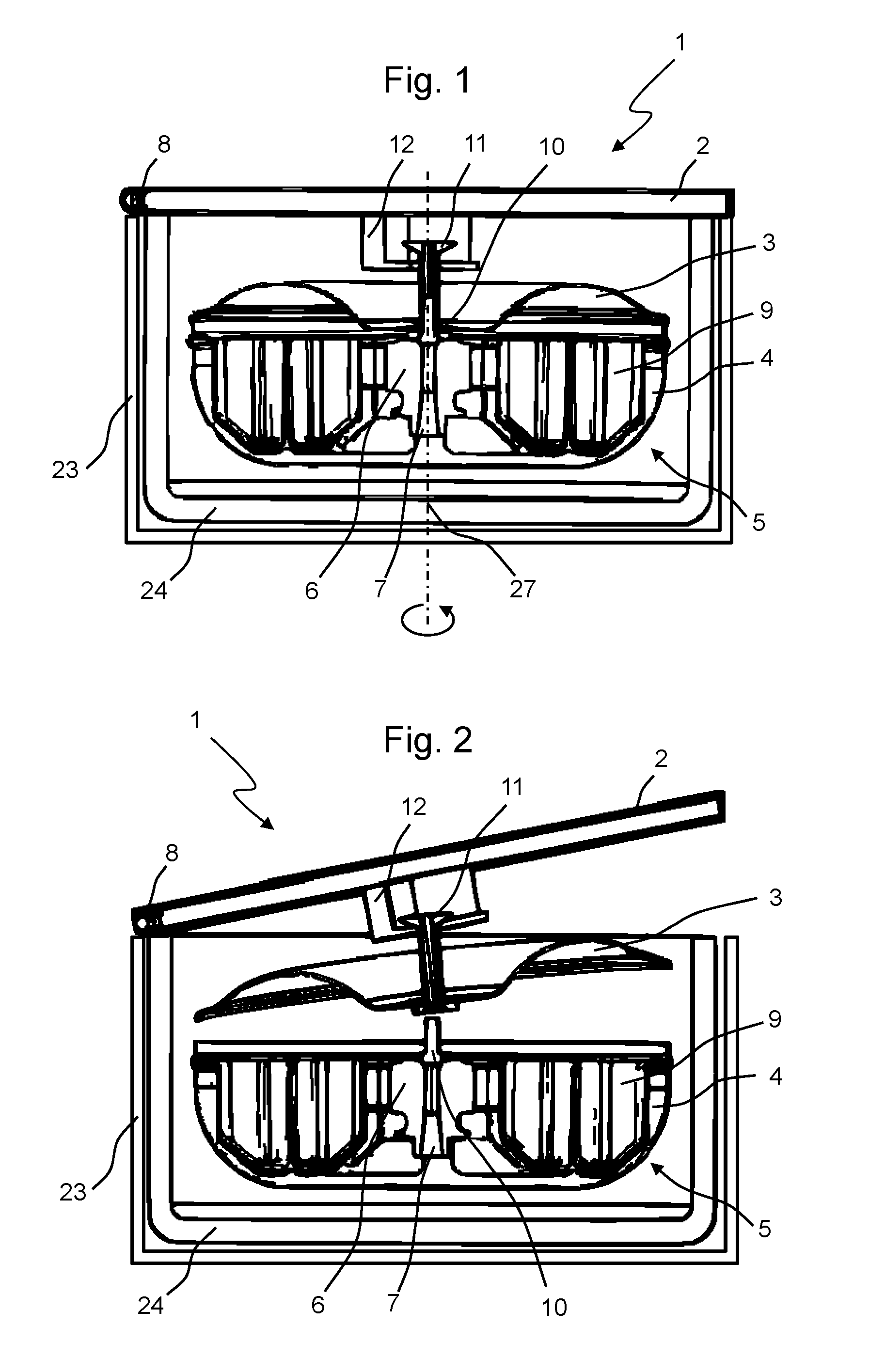
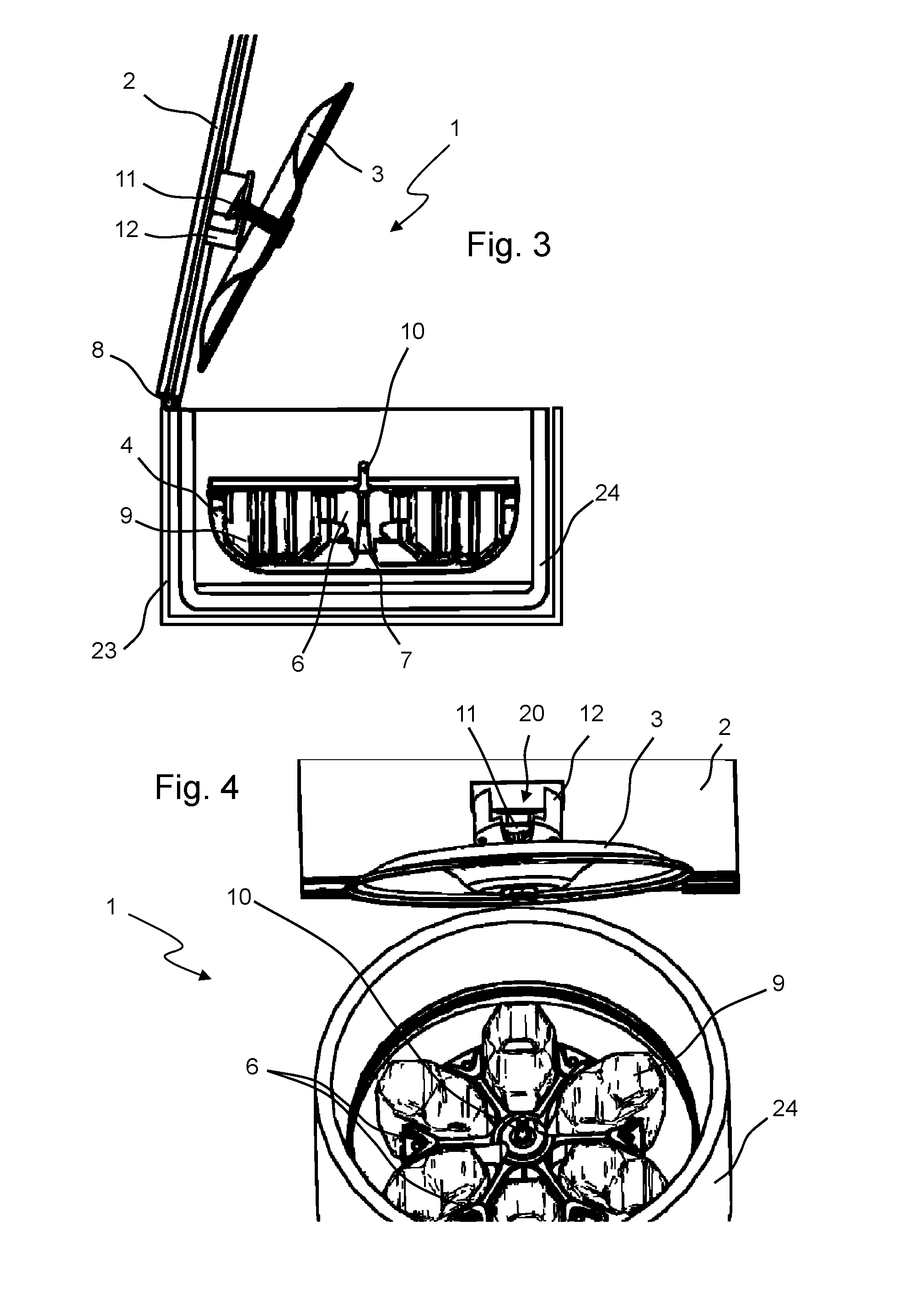
[0033]FIG. 1 shows a centrifuge 1 with a housing 23 comprising a centrifuge lid 2. The centrifuge lid 2 is a hinged lid and can be opened or folded open upwardly via the hinge 8. A guard ring 24, which is designed as a burst protection, and a rotor 5 are disposed within the housing 23. Further components that are not shown, such as a drive motor, a cooling compressor and a ventilation system, are also disposed within the housing 23, however these components are of minor importance for the present invention as they do not differ from corresponding prior art devices. The rotor 5 has a receptacle 7 for the drive shaft of the motor (both are not shown). The rotor 5 can be rotated about the axis of rotation 27 by the centrifuge motor. The rotor 5 has a rotor cross 6, a vessel 4 and centrifuge buckets 9 for accommodating sample vessels. Further, a centering pin 10, which will be described in more detail below, is arranged on the rotor 5.

[0034]The centrifuge 1 shown in FIG. 1 is in the clo...


PUM


Abstract

The present invention relates to a centrifuge, in particular, a laboratory centrifuge, with a housing comprising a centrifuge lid, which delimits the centrifuge to the outside, a rotor and a rotor cover for closing the rotor, a connecting device comprising a holding arm and a holder being provided, via which the rotor cover and the centrifuge lid can be detachably connected with each other in such a way that the rotor cover is lifted off of the rotor upon opening of the centrifuge lid and is placed on the rotor upon closing the centrifuge lid. The holding arm is detachably and movably mounted in the holder during opening and closing of the centrifuge lid, and the holding arm and the holder are spaced via a gap space when the centrifuge lid is closed.

Description

CROSS-REFERENCE TO RELATED APPLICATIONS[0001]The present application claims priority under 35 U.S.C. §119 of German Patent Application No. 10 2014 008 256.3, filed Jun. 6, 2014, the disclosure of which is hereby incorporated herein by reference in its entirety.FIELD OF THE INVENTION[0002]The present invention relates to a centrifuge and, in particular, to a laboratory centrifuge having a housing comprising a centrifuge lid that delimits the centrifuge to the outside, a rotor and a rotor cover for closing the rotor.BACKGROUND OF THE INVENTION[0003]Such centrifuges are widely used in laboratories, particularly in life sciences and related fields. They are used for separation of substance mixtures, for example, suspensions, emulsions or gas mixtures. Besides organic and inorganic substances, for example, microorganisms or cells can be separated from suspensions. The mixtures to be separated are fixed in containers on the rotor and accelerated on a circular path. Due to differing mass i...

Claims


Application Information

Patent Timeline
IPC IPC(8): B04B7/02
CPCB04B2007/025B04B7/02
Inventor BALLHAUSE, NORMAN
Owner THERMO ELECTRONICS LED GMBH
Why Eureka
Try Eureka