Peg Press-Fitting Structure for Connector

Active Publication Date: 2015-12-03
YAZAKI CORP
View PDF17 Cites 1 Cited by
  • Summary
  • Abstract
  • Description
  • Claims
  • Application Information

AI Technical Summary

Benefits of technology

The patent text describes a structure for fixing a peg to a circuit board using a press-fit connection. The peg is fitted into a slot in the housing and a regulating projection ensures that the peg is securely positioned. This helps to stabilize the contact between the peg and a metal member for grounding, improving the reliability of the electrical connection. The technical effect of this structure is to provide a reliable and stable grounding connection for the press-fitted peg.

Problems solved by technology

However, if the pegs are positioned only by recognizing that the pegs project from the housing, when the pegs are excessively pushed into the peg attaching slots of the housing, the press-fitting positions may become out of the appropriate range.
If the press-fitting positions are displaced like this, there is a problem which is that when the cable side connector is engaged with the board side connector, the contacting positions where the grounding member of the cable side connector and the pegs contact may be displaced, and the reliability of the grounding connection decreases.

Method used


Image

  • Peg Press-Fitting Structure for Connector
  • Peg Press-Fitting Structure for Connector
  • Peg Press-Fitting Structure for Connector

Examples


Embodiment Construction

[0032]Below, an embodiment of the present invention is described with reference to the figures.

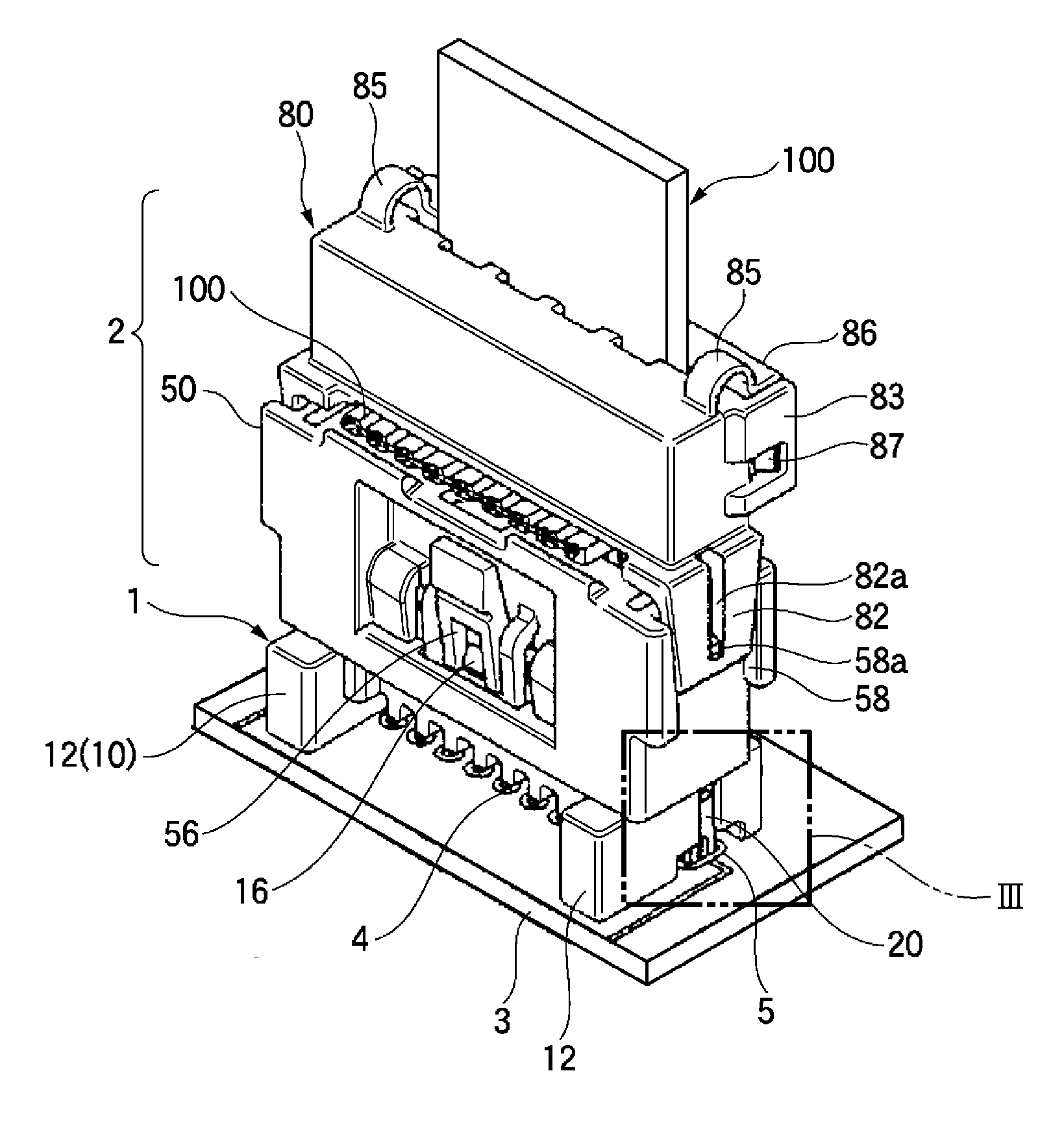
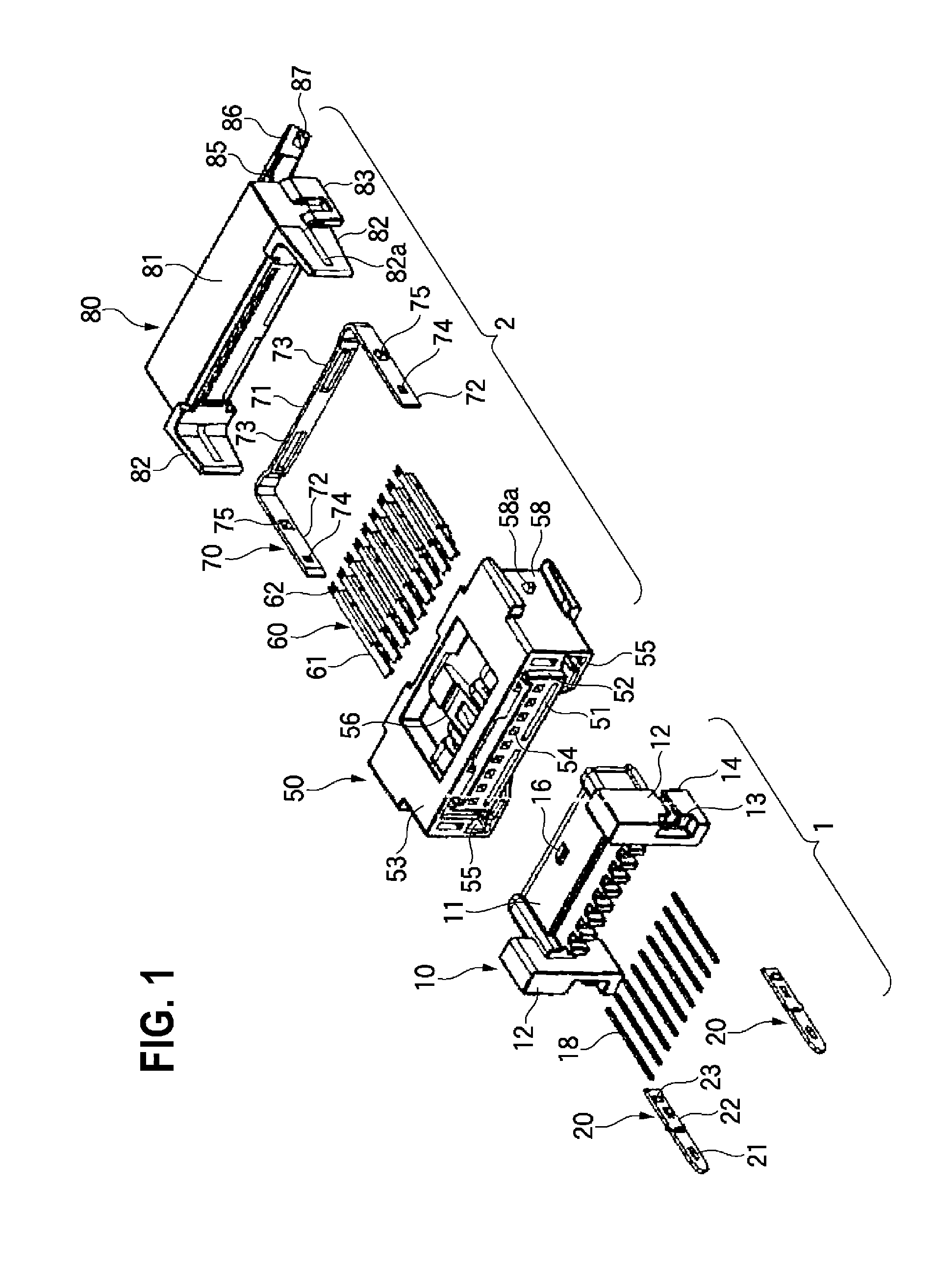
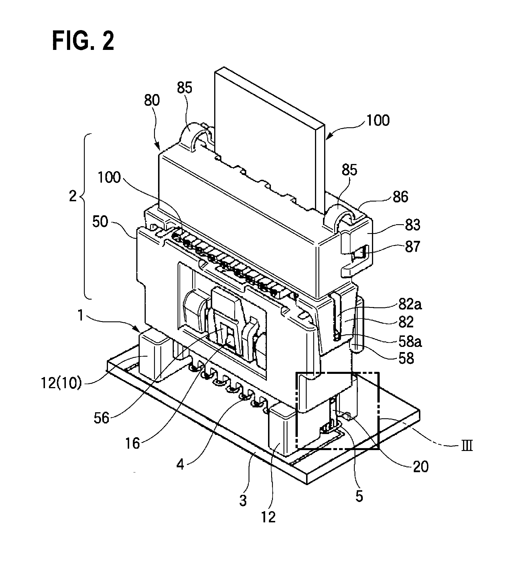
[0033]FIG. 1 is an exploded perspective view of a connector device in which a peg press-fitting structure of the embodiment of the present invention is included. FIG. 2 is a perspective view which indicates that the connector device in which the peg press-fitting structure of the embodiment of the present invention is included is in an engaged state. FIG. 3 is an expanded sectional view of part of the peg press-fitting structure of the embodiment that is applied to the III portion of FIG. 2. FIG. 4 is a side view which indicates that the connector device in which the peg press-fitting structure of the embodiment of the present invention is included is in the engaged state. FIG. 5 is a sectional view taken along a line indicated by the V-V arrows of FIG. 4. FIG. 6 is an enlarged view of the VI portion of FIG. 5.

[0034]As shown in FIGS. 1 and 2, the connector device includes a board side conn...


PUM


Abstract

A peg press-fitting structure for a connector includes a peg which is made from a metal plate to fix a housing of the connector to a circuit board, and which is attached to the housing by being press-fitted from the distal end of the peg into a peg attaching slot of the housing of the connector. The housing is provided with an end wall where an entrance of the peg attaching slot opens. A press-fitting position regulating projection, which regulates the press-fitting position of the peg by abutting against the end wall of the housing where the entrance of the peg attaching slot opens, is provided closer to the base end of the peg than a press-fitted portion of the peg that is press-fitted into the peg attaching slot.

Description

CROSS REFERENCE TO RELATED APPLICATIONS[0001]This application is a continuation of PCT application No. PCT / JP2014 / 053360, which was filed on Feb. 13, 2014 based on Japanese Patent Application (No. 2013-025745) filed on Feb. 13, 2013, the contents of which are incorporated herein by reference.BACKGROUND OF THE INVENTION[0002]1. Field of the Invention[0003]The present invention relates to a peg press-fitting structure to fix the housing of a connector to a circuit board.[0004]2. Related Art[0005]It is known (for example, refer to JP-A-2010-176958) to use pegs made of metal which can perform the grounding connection of a board side connector at the same time when the board side connector (receptacle) is fixed to a circuit board.[0006]In this case, the pegs made of metal are press-fitted and fixed into peg attaching slots which a connector housing is formed with, and when the pegs are fixed to the circuit board, the pegs are electrically connected to a grounding circuit of the circuit b...

Claims


Application Information

Patent Timeline
IPC IPC(8): H01R12/70H01R13/6581
CPCH01R13/6581H01R12/7011H01R12/596H01R12/675H01R12/79H01R13/5829H01R13/6582
Inventor SAWAIRI, KAORUHAMADA, KEIJI
Owner YAZAKI CORP
Why Eureka
Try Eureka