
Automatic configuration of control device user interface in a home automation system

a technology of home automation and user interface, which is applied in the field of home automation systems, can solve the problems of significant modifications, add to the overall cost of a home automation system, and are typically time-consuming and error-prone, and achieve the effect of reducing the installation time (and thus the overall cost of the home automation system), and reducing the potential for human error introducing bugs

Active Publication Date: 2015-11-26
SAVANT SYST INC
View PDF3 Cites 35 Cited by
  • Summary
  • Abstract
  • Description
  • Claims
  • Application Information

AI Technical Summary

Benefits of technology

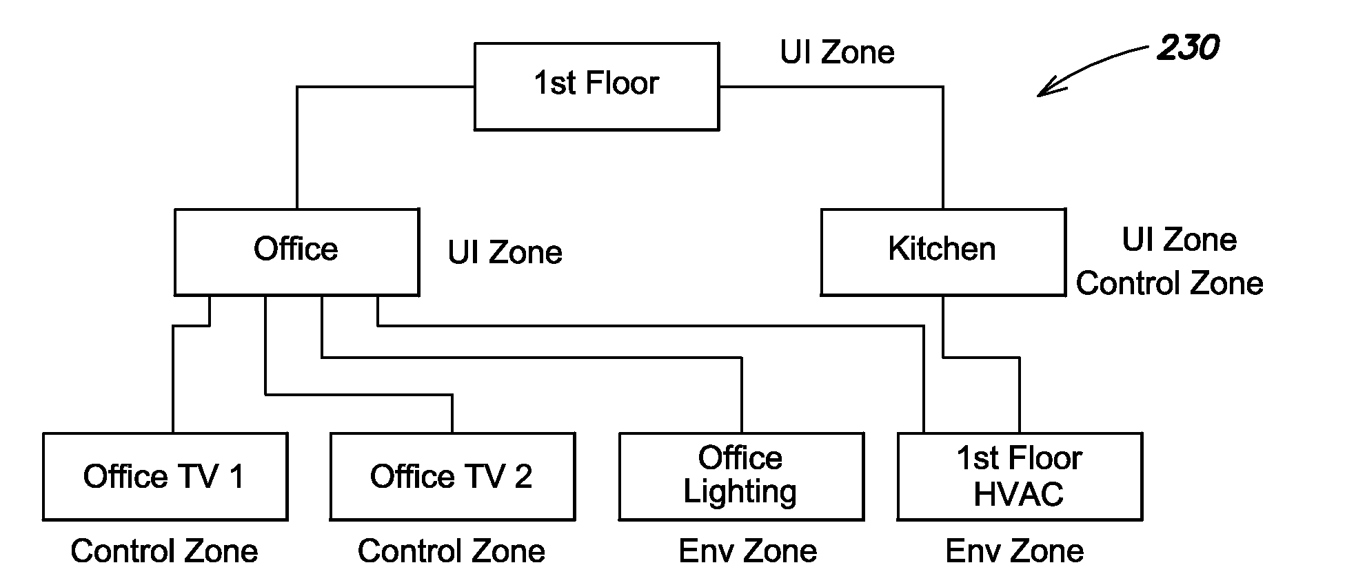
This patent describes a technique for creating a home automation system using control devices that don't require a custom user interface (UI). The system is set up by an installer and when a user activates a control device, it automatically generates its own custom UI based on the system's configuration. This eliminates the need for the installer to manually alter the UI for each new configuration or reconfiguration. This technique reduces the time and cost of the system and also reduces the likelihood of bugs due to human error.

Problems solved by technology

Even when UI templates are available, installers often need to make significant modifications to them before they are appropriate for use on a control device.
Among other shortcomings, it is typically time consuming and error prone.
The use of installer time generally adds to the overall cost of a home automation system, placing home automation beyond the reach of many consumers.
Further, the potential for errors may lead to unreliability and user dissatisfaction with the home automation system.

Method used


Image

  • Automatic configuration of control device user interface in a home automation system
  • Automatic configuration of control device user interface in a home automation system
  • Automatic configuration of control device user interface in a home automation system

Examples


Embodiment Construction

An Example Home Automation System

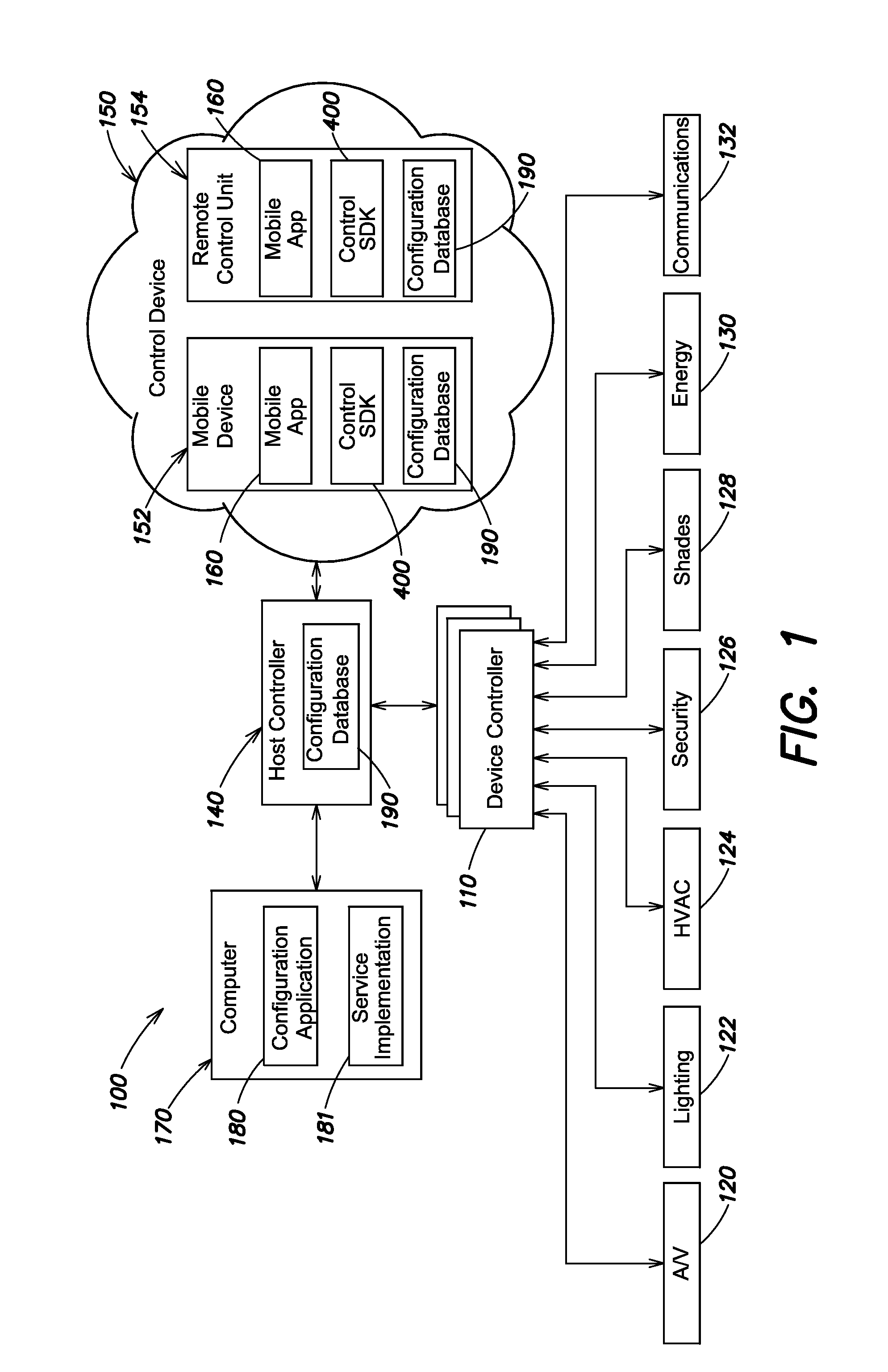
[0025]FIG. 1 is a block diagram of an example architecture of a home automation system 100 operable to control devices about a structure (e.g., a home or commercial building). At the core of the system 100 are one or more device controllers 110 and a host controller 140. The device controllers 110 operate to switch signals between and provide low-level control to a variety of interconnected devices and / or subsystems 120-132. The host controller 140 controls and monitors operations of the device controllers 110, as well as provides user UI interpretation, system administration and monitoring, and / or other high-level control functions. Custom UIs for interacting with the home automation system 100 may be displayed to users on a variety of types of control devices 150. Further, the home automation system 100 may be configured by an installer (e.g., prior to initial use, or upon a change to the system) using a configuration application 180 that may be ex...


PUM


Abstract

In one embodiment, a technique is provided for automatically generating a custom user interface (UI) of a control device usable to control a home automation system. A configuration database is maintained, for example, on a host controller, of the home automation system. The configuration database stores logical representations that describe a configuration. The configuration database is transferred (e.g., downloaded) to a control device. The control device accesses the configuration database for one or more of the logical representations, and translates returned information related to the one or more of the logical representations to UI element, using predefined mappings. The controll device then displays the UI elements as a custom UI.

Description

BACKGROUND[0001]1. Technical Field[0002]The present disclosure relates generally to home automation systems and more specifically to the user interfaces (UIs) of control devices used in home automation systems.[0003]2. Background Information[0004]Home automation systems are becoming increasingly popular in both residential and commercial buildings. Such systems may be capable of controlling, switching data between, and otherwise interacting with a wide variety of devices, including audio / video devices (A / V) devices, heating ventilation and cooling (HVAC) devices, security devices, energy conservation devices, communications devices, telephony devices, and / or other types of devices. Often, a user may indicate desired control to a home automation system utilizing one or more control devices, for example, mobile devices (such as smartphones or tablet computers), remote control units that include a display screen (e.g., a touch sensitive display screen) upon which a user interface (UI) ...

Claims


Application Information

Patent Timeline
IPC IPC(8): H04L12/28G06F17/30G06F3/0484
CPCH04L12/282G06F17/30477G06F3/0484H04L12/28H04L12/281G06F9/451G06F16/00G06F16/2455G06F3/14H04L41/22
Inventor TATZEL, DAVID W.JACOBSON, ARTHUR A.CIPOLLO, NICHOLAS J.RONQUILLO RODRIGUEZ, JOSE J.
Owner SAVANT SYST INC
Learn More