
Joint connector

a connector and connector technology, applied in the direction of securing/insulating coupling contact members, coupling device connections, electric discharge lamps, etc., can solve the problems of difficult to determine whether the contact between the terminal fittings and the bus bars is cancelled, and cannot be detected

Inactive Publication Date: 2015-11-26
YAZAKI CORP
View PDF0 Cites 10 Cited by
  • Summary
  • Abstract
  • Description
  • Claims
  • Application Information

AI Technical Summary

Benefits of technology

The present invention is about a joint connector that can detect the installation of terminal fittings and improve their retention in the connector housing. The joint connector includes a connector housing with terminal accommodation chambers, locking lances, bus bars, and a front holder. The front holder has a holder main body with integrated bus bars and lance deformation prevention portions that prevent the elastic deformation of the locking lances. This prevents disengagement of the terminal fittings and locking lances even in the case of impact. The bus bars and lance deformation prevention portions are integrated with the holder main body, reducing the assembling task and manufacturing cost. The joint connector prevents water and other liquids from entering the connector housing and ensures a secure attachment of the front holder to the connector housing.

Problems solved by technology

However, in the above joint connector, the locking convex portions are only simply inserted into the lock holes of the bus bars.
Thus, contact between the terminal fittings and the bus bars is sometimes cancelled by some impact (such as vibration of a vehicle).
In the above joint connector, it is difficult to determine whether or not the terminal fittings are completely installed in the terminal accommodation chambers (whether or not the locking convex portions are engaged with the lock holes), and an installment state of the terminal fittings into the terminal accommodation chambers (including a half-installment state) cannot be detected.

Method used


Image

  • Joint connector
  • Joint connector
  • Joint connector

Examples


Embodiment Construction

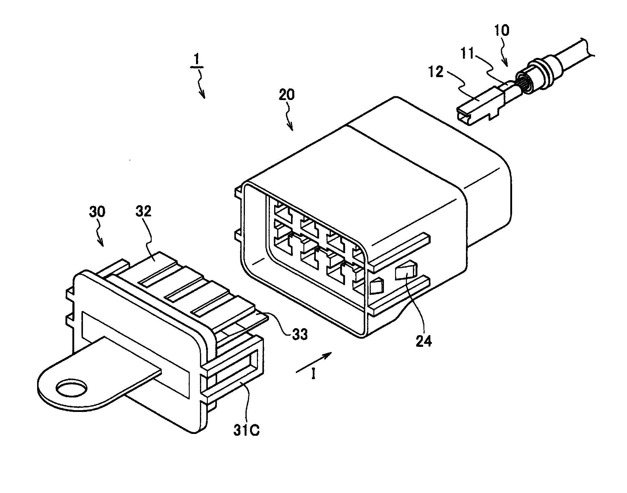
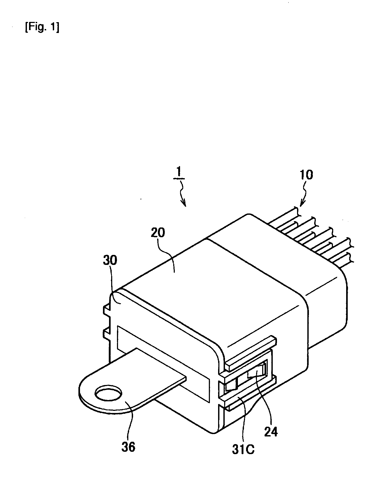
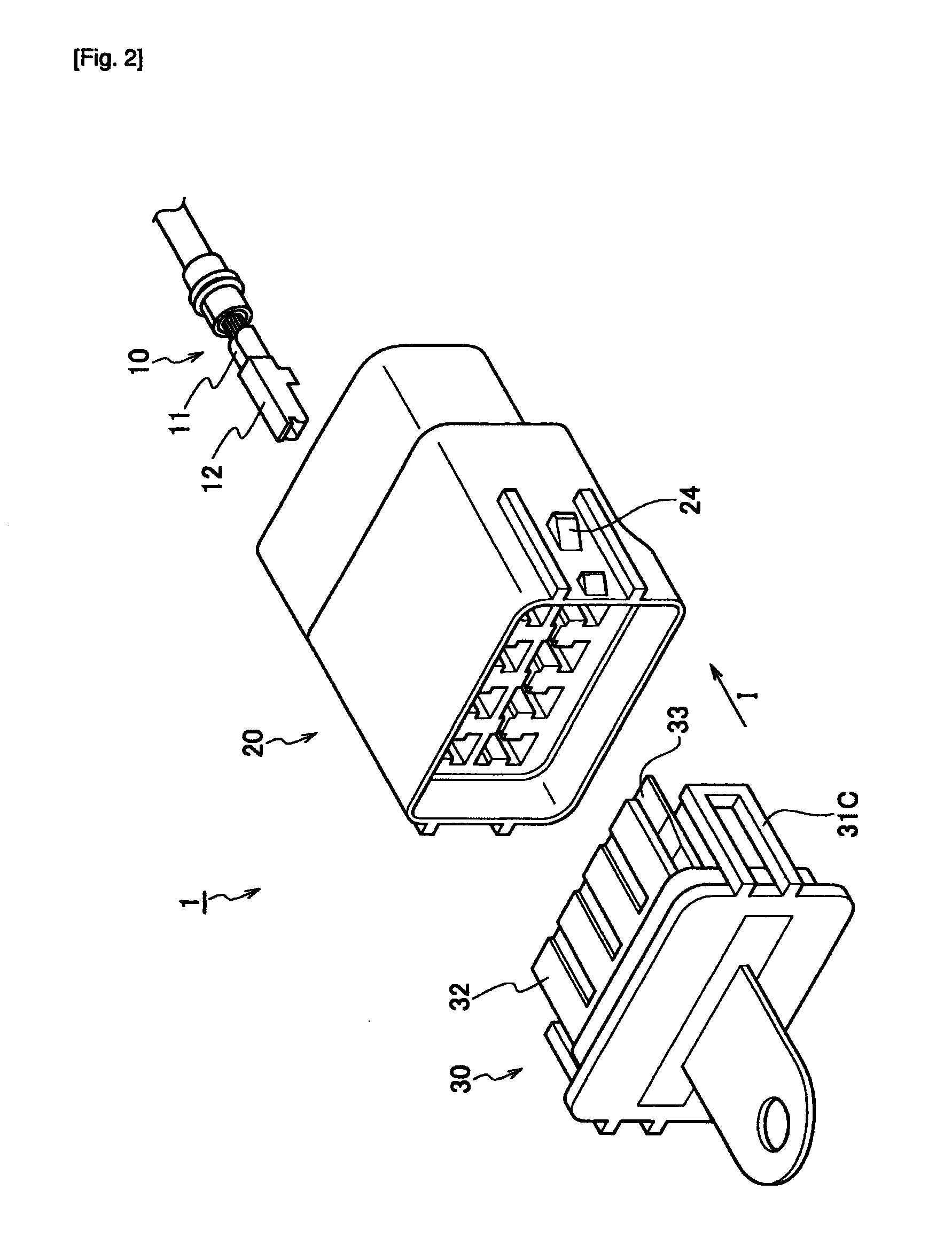
[0023]A joint connector according to an embodiment of the present invention will be described with reference to the drawings. Specifically, (1) a configuration of the joint connector, (2) a configuration of a front holder, (3) an installment method of the front holder, (4) operations and effects, and (5) other embodiments will be described.

[0024]It should be noted that in the following description of the figures, the same or similar parts will be given the same or similar reference signs. However, note that the figures are schematic ones and ratios and the like in terms of size are different from reality.

[0025]Therefore, specific size and the like should be determined in consideration with the following description. Relationships or ratios in terms of size can be different between the figures.

(1) Configuration of Joint Connector

[0026]A configuration of a joint connector 1 according to the present embodiment will be described with reference to the drawings. FIG. 1 is a perspective vi...


PUM


Abstract

A joint connector includes a connector housing having terminal accommodation chambers configured to accommodate terminal fittings and having elastically-deformable locking lances configured to engage with the corresponding terminal fittings, bus bars configured to connect the terminal fittings to each other, and a front holder to be installed in the connector housing from an opposite side to a side where the terminal fittings are inserted. The front holder has a holder main body integrated with the bus bars and lance deformation prevention portions configured to prevent elastic deformation of the locking lances. In an engagement state of the terminal fittings and the locking lances, the lance deformation prevention portions are configured to be inserted into spaces in which the locking lances are deflected.

Description

TECHNICAL FIELD[0001]The present invention relates to a joint connector including a connector housing provided with a plurality of terminal accommodation chambers in which a plurality of terminal fittings is accommodated, and bus bars for connecting the plurality of terminal fittings.BACKGROUND ART[0002]In general, in a joint connector, a plurality of terminal fittings attached to terminals of electric wires is respectively accommodated in a plurality of terminal accommodation chambers formed in a connector housing. The terminal fittings accommodated in the terminal accommodation chambers are connected by bus bars.[0003]Such terminal fittings are proposed in Patent Literature 1, and locking convex portions to be inserted into lock holes formed in the bus bars are provided. Accordingly, the terminal fittings are prevented from being drawn out from the terminal accommodation chambers.CITATION LISTPatent Literature[0004][PTL 1] JP 11-329569 ASUMMARY OF INVENTION[0005]However, in the ab...

Claims


Application Information

Patent Timeline
IPC IPC(8): H01R13/42
CPCH01R13/42H01R13/4223H01R13/4364H01R13/52H01R31/08
Inventor HAMAI, TSUYOSHIMURO, TAKASHINAGAYOSHI, TOMIHIKO
Owner YAZAKI CORP
Learn More