
Monitoring device, monitoring system, and monitoring method

a monitoring device and monitoring system technology, applied in the field of monitoring devices and monitoring systems, can solve problems such as the burden on users becoming larg

Active Publication Date: 2015-11-26
PANASONIC INTELLECTUAL PROPERTY MANAGEMENT CO LTD
View PDF0 Cites 26 Cited by
  • Summary
  • Abstract
  • Description
  • Claims
  • Application Information

AI Technical Summary

Benefits of technology

This patent describes a monitoring device that can detect a person in a camera and analyze their position in relation to other people. It can then create a mask image that represents the area where the person is located. The device then generates and outputs a video stream that shows the person in a different area. This technology aims to improve image analysis and video monitoring for safety and security purposes.

Problems solved by technology

However, in a state where a plurality of people overlap when viewed from a camera, a person area which is detected from moving images is configured by a plurality of people, that is, a state is detected where the image area of the plurality of people is continuous, in such a case, there is a problem in that just from viewing the mask image it is not possible to simply determine the state of people from the mask image without being certain whether there is only one person or if there is a plurality of people, and in particular, there is a problem in that a burden on a user becomes large in a case where the moving images span a long period of time, and a technique is desired where it is possible to effectively perform work where the behavior of people is ascertained.

Method used


Image

  • Monitoring device, monitoring system, and monitoring method
  • Monitoring device, monitoring system, and monitoring method
  • Monitoring device, monitoring system, and monitoring method

Examples


first exemplary embodiment

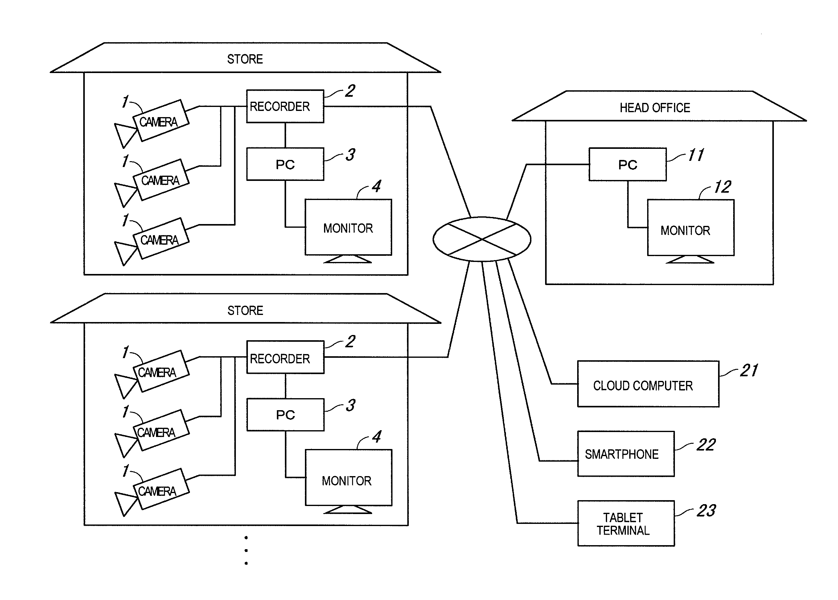
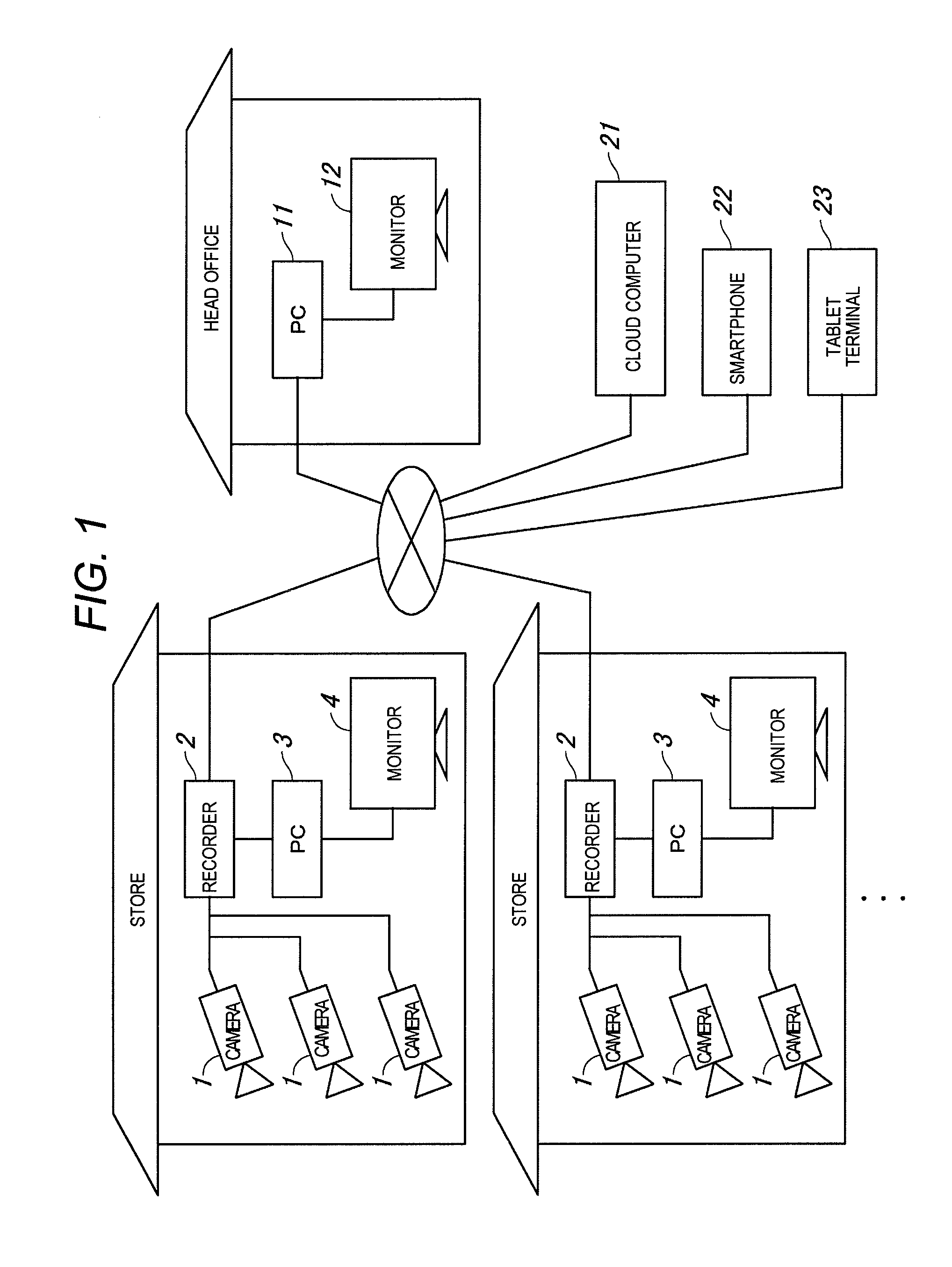
[0057]FIG. 1 is a configuration diagram of the entirety of a monitoring system according to a first embodiment; The monitoring system is an assembly which targets retail chain-stores such as convenience stores, and is provided with camera 1, a plurality of which are provided in each store, recorder (moving image storage device) 2, PC (a monitoring device) 3, and monitor (display device) 4, and PC 11 and monitor 12 which are provided in the general head office of the plurality of stores.

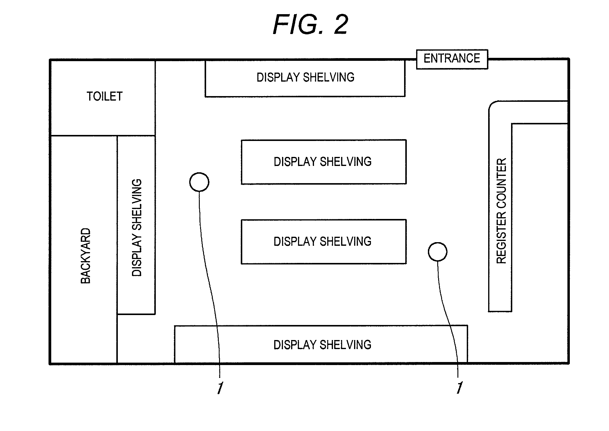
[0058]Camera 1 is installed at appropriate locations inside the store, the inside of the store (the monitoring area) is captured by camera 1, and the moving images obtained thereby are recorded on recorder 2. On PC 3 which is provided in the store and PC 11 which is provided in the head office, it is possible to access the moving images inside the store, which are captured by camera 1, in real time, in addition, it is possible to access moving images inside the store from the past which are recorded i...

second exemplary embodiment

[0109]A second embodiment will be described below. Points which are not specifically referenced are the same as the first embodiment.

[0110]FIG. 10 is a functional block diagram illustrating a schematic configuration of PC 3 in a monitoring system according to the second embodiment. In the second embodiment, person image analyzer 32 is provided with person tracker 39 in addition to person detector 37 and area state determinator 38.

[0111]Person detector 37 detects a person frame (a rectangle which encloses the upper half of the body of a person) in each frame of the captured moving images, and positional information of the person frame (information which relates to the position and the size of the person frame) is acquired. Person tracker 39 associates the positional information of the person frame which is acquired in person detector 37, that is, a process is performed where the positional information of the person frame is acquired in each frame (time) which relates to the same pers...

third exemplary embodiment

[0118]A third embodiment will be described below. Points which are not specifically referenced are the same as the first embodiment.

[0119]FIG. 12 is a functional block diagram illustrating a schematic configuration of PC 3 in a monitoring system according to the third embodiment. In the third embodiment, in the same manner as the first embodiment, it is possible to display mask images with separate area states (group and standalone), furthermore, it is possible to display mask images with separate attributes (male and female), and person image analyzer 32 is provided with attribute determinator 40 in addition to person detector 37, person tracker 39, and area state determinator 38.

[0120]In attribute determinator 40, attributes are determined for each person who the person area is configured by, and the attributes of the entirety of the person area are determined based on the attributes of each person. The determination process for attributes of each person which is performed by attr...


PUM


Abstract

A monitoring device is provided with a person image analyzer which has a person detector which detects a person from captured moving images and acquires positional information which relates to a person area, and an area state determinator which determines an area state which indicates the state of people in the person area based on the positional information, a mask image setter which sets the mask image which corresponds to the area state, and a moving image output controller which generates and outputs output moving images where the person area is changed to the mask image which corresponds to the area state based on the positional information and the area state which are output from the person image analyzer.

Description

BACKGROUND OF THE INVENTION[0001]1. Field of the Invention[0002]The present invention relates to a monitoring device, a monitoring system, and a monitoring method where output moving images, where a person area which is detected from captured moving images in a monitoring area is changed to a mask image, are generated and output.[0003]2. Description of the Related Art[0004]In a store such as a convenience store, a monitoring system where cameras which capture the inside of the store are installed and people inside the store are monitored using moving images from the cameras has become widespread, but in a case where captured moving images are used with an object other than the object of monitoring, that is, marketing analysis or service improvement, it is necessary to protect customer privacy.[0005]With respect to the demand to protect customer privacy, in the related art a technique is known where a person area in a moving image which is captured using a camera is changed to a spec...

Claims


Application Information

Patent Timeline
IPC IPC(8): G06K9/00H04N5/272H04N7/18G06K9/74
CPCG06K9/00342G06K9/00369G06K9/00778H04N2005/2726H04N5/272H04N7/181G06K2207/1012G06K9/74H04N5/275G06T11/60G06V40/23G06V20/53H04N23/61H04N23/635G08B13/19686H04N7/18G06V40/103G06T1/00
Inventor UETA, DAISUKEMATSUMOTO, YUICHIYOSHIDA, KAZUMA
Owner PANASONIC INTELLECTUAL PROPERTY MANAGEMENT CO LTD
Learn More