Resistive Force Sensing Circuit

a sensing circuit and resistive force technology, applied in the field of resistive force sensing circuits, can solve the problems of consuming more power, affecting the output value, and affecting the accuracy of data, so as to reduce interference, reduce leakage current, and simplify circuit structure and scanning method

Active Publication Date: 2015-11-26
UNEO INC
View PDF5 Cites 7 Cited by
  • Summary
  • Abstract
  • Description
  • Claims
  • Application Information

AI Technical Summary

Benefits of technology

The present invention provides a resistive force sensing circuit and a resistive force sensing apparatus that can detect force input at multiple points. This is achieved with a simple circuit configuration and algorithm. The circuit can use identical resistors in each unit, and digital-to-analog or analog-to-digital converters to solve voltage signal drop issues. The apparatus can also separate the sensing units to reduce interference, and use continuous side resistor parts to simplify production and reduce costs.

Problems solved by technology

This may cause “ghost point” phenomenon, when the system output a touch point at a location not touched.
Furthermore, the input device with a simple FSR array or matrix circuit may have high leakage currents between each input point or part, which may interfere with the output values and consume more power.
Although there have been many solutions to overcome the problems described above, such solutions usually utilize extra components such as op-amps, or complex algorithms.
Therefore, the costs of production and maintenance of such solutions inevitably become higher, in addition to increased chance of malfunction

Method used


Image

  • Resistive Force Sensing Circuit
  • Resistive Force Sensing Circuit
  • Resistive Force Sensing Circuit

Examples


second embodiment

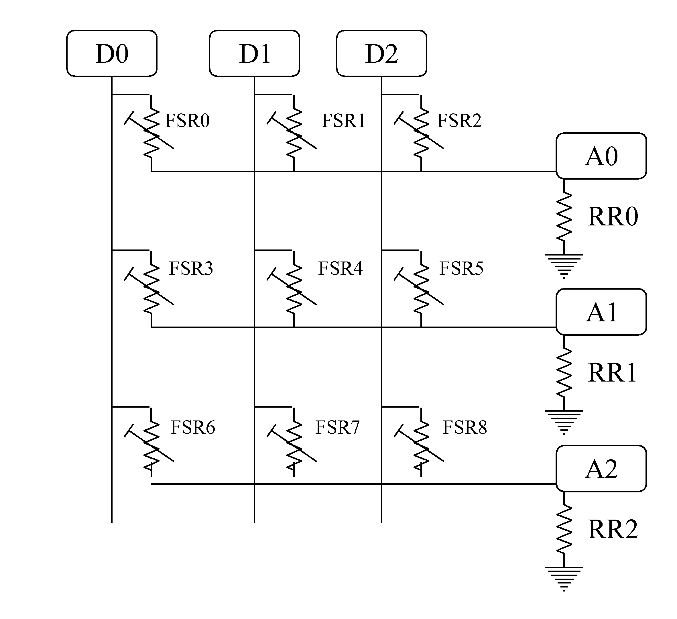
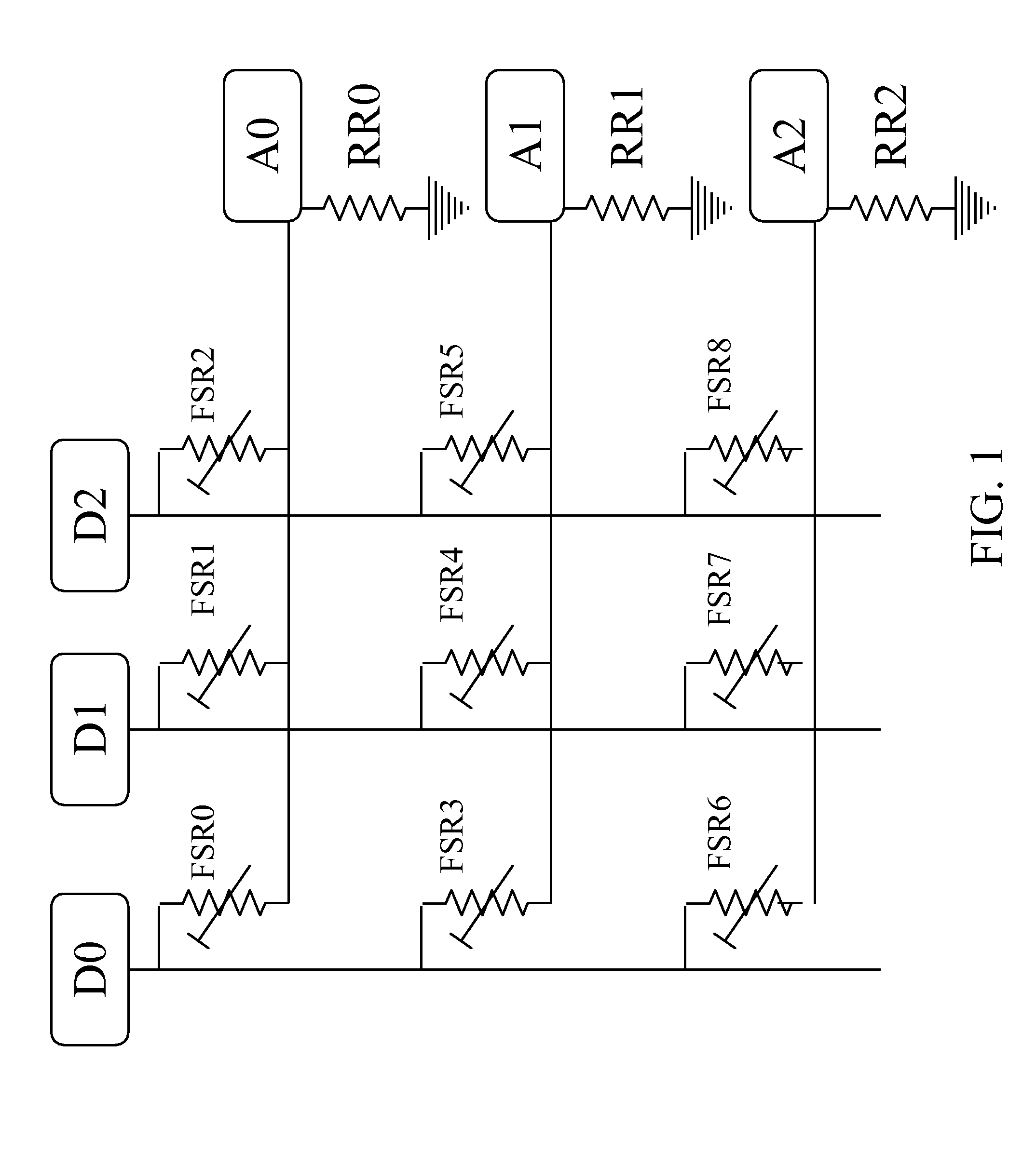
[0046]The similar scanning process as the conventional resistive force sensing circuit of FIG. 1 can be used on the resistive force sensing circuit of the present invention, but a simple algorithm is required to be performed to separate the output value resulted from different force-sensing resistors FSR0 to FSR8. One of examples of such algorithms will be described in reference with drawings hereafter. In that case, the sensor circuit outputs which are not driven by the output driving circuit are grounded. Since the first and second resistors R01 to R81 and R02 to R82 exist, the grounded resistors in the conventional resistive force sensing circuit are not required.

[0047]FIGS. 5A and 5B are schematic circuit diagrams of equivalent circuits of the resistive force sensing circuit of FIG. 4 for two different scanning configurations. With reference to FIGS. 5A and 5B, the scanning method used in this embodiment will be described in detail. In following description, the scanning step wh...

first embodiment

[0053]It is worth to mention that the configuration of the sensor circuit inputs and the gaps of two adjacent sensor circuit outputs is not necessary a matrix. With reference to FIG. 7 for a schematic circuit diagram of a resistive force sensing circuit for sensing forces at multiple points according to the forth embodiment of the present invention. In FIG. 7, the sensor circuit inputs D0, D1 and D2 are configured as concentric rings, and the sensor circuit outputs A0, A1 and A2 are configured as radial lines. The electrical connection between the sensor circuit inputs D0, D1 and D2, the sensor circuit outputs A0, A1 and A2, the force-sensing resistors FSR0 to FSR8, and the first and second side resistors R01 to R81 and R02 to R82 are similar to the circuit in FIG. 3. The force-sensing resistor, the first and second side resistors can still form a resistor unit by connecting each other at one point, for example, the force-sensing resistor FSR3, and the first and second side resistor...

sixth embodiment

[0070]FIG. 11 is a schematic top view of a resistive force sensing apparatus with multiple point force sensing function according to the present invention, and FIG. 12 is a schematic view of one resistor unit and electrodes connected to the resistor unit structure of the resistive force sensing apparatus in a circle of a dotted line of FIG. 11.

[0071]In this embodiment, it can be seen that not only the structure of the fifth embodiment but also other structures can realize the resistive mentioned above, such as the structure of the resistive force sensing apparatus of the sixth embodiment of the present invention. As showed in FIG. 11, the resistive structure included in the resistive force sensing apparatus can be seen as a 4*4 matrix, and the method to define the matrix is similar to the fifth embodiment of the present invention in FIG. 9. It is worth to mention that the resistor structures 00 to 80 of the sixth embodiment in FIG. 11 are substantially separated from each other, in ...


PUM


Abstract

A resistive force sensing circuit and a resistive force sensing apparatus. The circuit includes a plurality of sensor circuit inputs, a plurality of sensor circuit outputs; and a plurality of resistor units. Each of the resistor units includes a force-sensing resistor, a first side resistor, and a second side resistor. The first terminals of the force-sensing resistor, the first side resistor and the second side resistor are electrically connected to each other at one node, a second terminal of the force-sensing resistor is electrically connected to one of the sensor circuit inputs, and second terminals of the first side resistor and the second side resistor are electrically connected to two adjacent sensor circuit outputs, respectively. The first side resistor and the second side resistor are a pair of resistors with substantially equal resistance. The apparatus includes structures to realize the function of the resistive force sensing circuit.

Description

BACKGROUND OF THE INVENTION[0001]1. Field of the Invention[0002]The present invention generally relates to a resistive force sensing circuit for sensing physically-applied inputs and a resistive force sensing apparatus thereof.[0003]2. Description of the Related Art[0004]Currently, touch sensing has been successfully applied in many fields, such as portable device input, medical monitor and electronic point of sale (POS) system. Touch control mechanisms include: resistive, capacitive, optical, etc. Resistive sensing has an advantage in its ability to combine touch and force sensing through force-sensing resistor (FSR). Although early resistive touch control technique can only detect one touch point, various solutions can offer multi-touch or force-sensing points recently.[0005]However, in many cases, when an input device with a simple FSR matrix circuit contains multi-point force-sensing function, the output value can be affected by the number of input pressure points and force leve...

Claims


Application Information

Patent Timeline
Patent Type & Authority Applications(United States)
IPC IPC(8): G06F3/045G06F1/16G06F3/041
CPCG06F3/045G06F3/0416G06F3/0414G06F2203/04104G06F1/16G06F3/04166
Inventor CHERN, YANN-CHERNGCHENG, CHIH-TSUNG
Owner UNEO INC
Why Eureka
Try Eureka