
Vacuum injection molding device and injection molding method using same

a technology of vacuum injection molding and injection molding method, which is applied in the field of vacuum injection molding device and injection molding method using same, can solve the problems of increased manufacturing cost, high initial cost, and deterioration of surface characteristics, and achieve the effects of reducing maintenance costs, enhancing productivity, and increasing the period of cleaning the mold

Inactive Publication Date: 2015-11-26
MPA TECH
View PDF1 Cites 3 Cited by
  • Summary
  • Abstract
  • Description
  • Claims
  • Application Information

AI Technical Summary

Benefits of technology

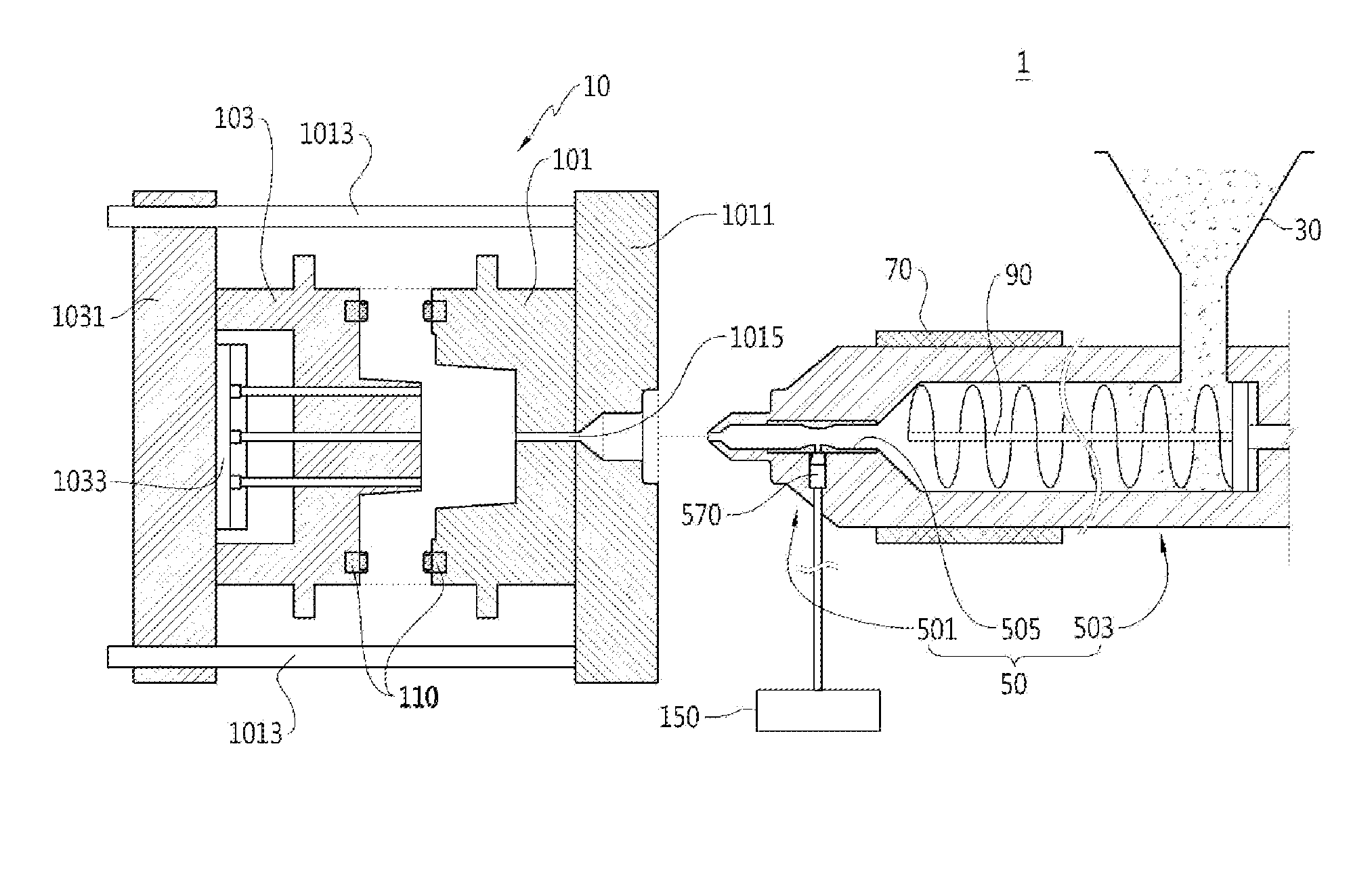
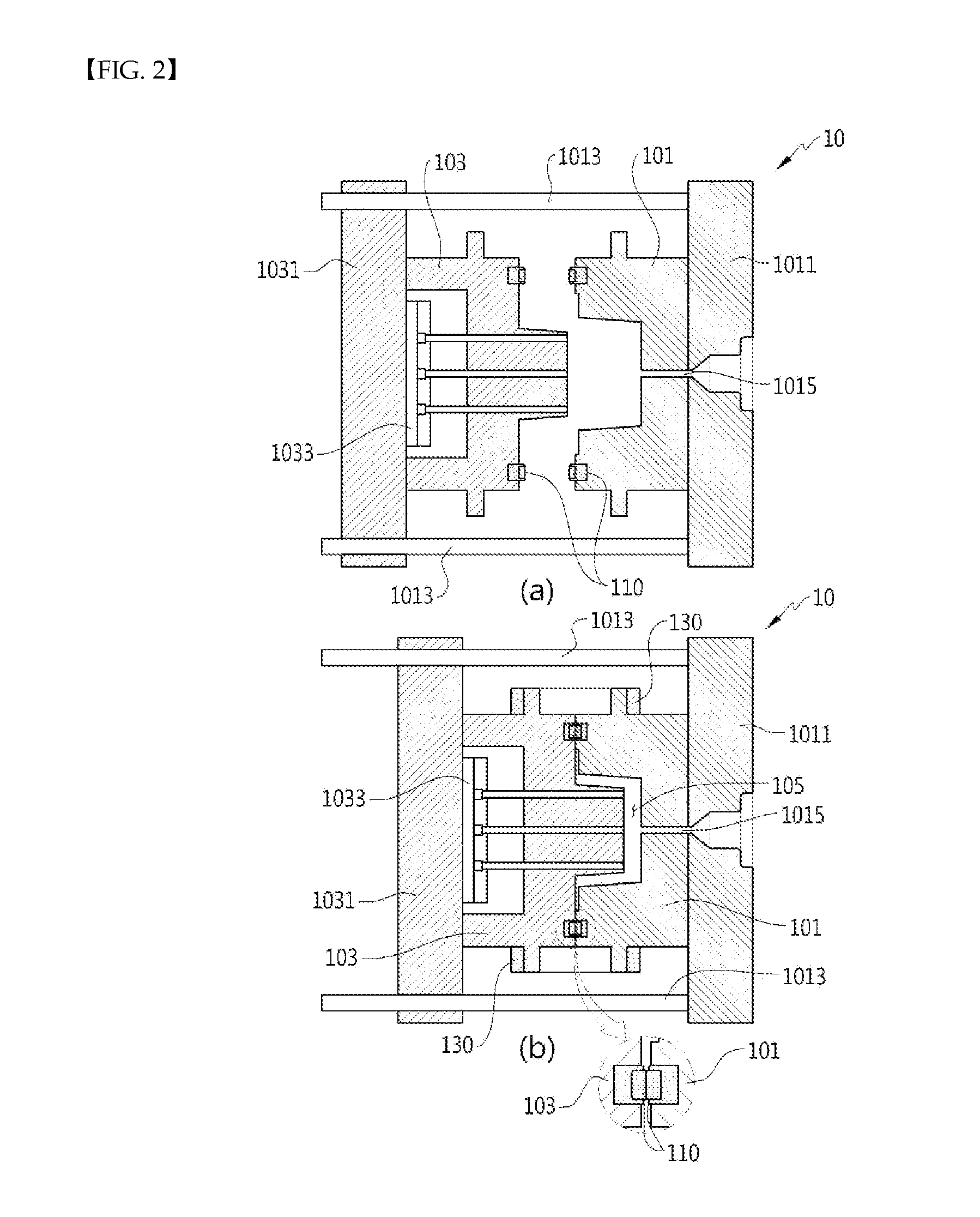
The present invention helps to remove foreign materials and gas from the injection cavity before injection molding, which reduces maintenance costs and increases productivity. The injection cavity is maintained in a vacuum state, which allows for better holding pressure and cooling during the molded product formation. Atmospheric pressure is then applied to the injection cavity to prevent water evaporation and improve product quality while reducing manufacturing costs. Gas is injected via the gas nozzle, which simplifies the process and improves operating performance and productivity.

Problems solved by technology

However, in such an injection molding device, while the resin goes through a plastication process of high temperature and is then injected into an injection cavity of atmospheric pressure, water is vaporized to obstruct flow of resin and adhesion of resin to molds so that surface characteristics may be deteriorated.
However, for this method, a drying device which is specially manufactured is necessary, and this drying device causes high initial cost and also consumes substantial electricity so that manufacturing cost is increased and cost of the product is also increased.
Further, since the resin cannot be completely dried by the drying process by the drying device, water is evaporated during the forming process and this may cause the deformation of the exterior shape of the product and the quality problem.
Further, since foreign materials or gas may be remained in the molds which form the injection cavity due to repeated forming processes, the molds should be cleaned frequently and this increases maintenance cost and deteriorates the productivity.

Method used


Image

  • Vacuum injection molding device and injection molding method using same
  • Vacuum injection molding device and injection molding method using same
  • Vacuum injection molding device and injection molding method using same

Examples


Embodiment Construction

Technical Problem

[0009]The present invention has been made in an effort to provide a vacuum injection molding device which an injection cavity of atmospheric pressure is pressurized when the melted resin at high temperature is injected so as to prevent water in the resin from being evaporated and so as to remove foreign materials and gas inside the molds before the injection molding and so as to make the inside vacuum state, and the high-pressure gas is injected so that the molds and the molded product do not contact one another, thereby enhancing an exterior quality of the molded product, and an injection molding method using the same.

Technical Solution

[0010]A vacuum injection molding device according to an embodiment of the present invention includes: a first mold which is connected to an injection nozzle and is supplied with resin; a second mold which is coupled with the first mold so as to form an injection cavity; a fist seal member and a second seal member which surrounds an o...


PUM

PropertyMeasurementUnit
pressureaaaaaaaaaa
pressureaaaaaaaaaa
heat-resistingaaaaaaaaaa

Abstract

A vacuum injection molding device according to an embodiment of the present invention includes: a first mold which is connected to an injection nozzle and is supplied with resin; a second mold which is coupled with the first mold so as to form an injection cavity; a fist seal member and a second seal member which surrounds an outer side of a contacting surface of the first mold and the second mold and faces one another to contact one another; and a vacuum pump which exhausts gas in the injection cavity so as to form a vacuum state in the injection cavity. A gas exhausting passage is provided to communicate with the injection cavity via one or more of the first seal member and the second seal member, and the vacuum pump exhausts the gas in the injection cavity via the gas exhausting passage.

Description

TECHNICAL FIELD[0001]The present invention relates to a vacuum injection molding device of injecting high pressure gas into an injection cavity of vacuum state and subsequently injecting resin to form a product and an injection molding method using the same.BACKGROUND ART[0002]Generally an injection molding device is one of plastic molding devices and is a mechanical device which heats and melts resin which has been dehumidified and dried and injects the resin into molds, and cools the resin to coagulate to form molded products.[0003]In more detail, solid resin which is the raw material is melted using electrical heat, mechanical frictional heat, or the like, and the melted resin is injected into the molds which have desired shapes and is subsequently coagulated to form a formed product having a desired shape.[0004]However, in such an injection molding device, while the resin goes through a plastication process of high temperature and is then injected into an injection cavity of atm...

Claims


Application Information

Patent Timeline
Patent Type & Authority Applications(United States)
IPC IPC(8): B29C45/17B29C45/26B29C45/34
CPCB29C45/1701B29C45/2608B29C45/34B29C45/0025B29C45/174B29C2791/006B29C45/17
Inventor OH, SE YOON
Owner MPA TECH
Learn More