
Image processing device, image processing method, and control program

a control program and image processing technology, applied in image enhancement, image analysis, instruments, etc., can solve the problems of large soft matting load, large processing time, and inconsistency of transmission within the local region, so as to reduce processing load and reduce processing time. , the effect of removing fog in an imag

Active Publication Date: 2015-11-19
NIPPON SYSTWARE
View PDF2 Cites 5 Cited by
  • Summary
  • Abstract
  • Description
  • Claims
  • Application Information

AI Technical Summary

Benefits of technology

The present invention provides a way to quickly process images to remove fog with minimal effort. An image processing device, method, and control program are provided that can effectively remove fog from images. This provides a faster and more efficient way to process images, improving overall quality and efficiency.

Problems solved by technology

Therefore, the transmittance within the local region is not fixed but inconsistent.
Accordingly, the image processing device performs a uniformizing processing by soft matting in the method described in the aforementioned non-patent document 1, however, a processing load of soft matting is large and thereby, it takes much processing time.

Method used


Image

  • Image processing device, image processing method, and control program
  • Image processing device, image processing method, and control program
  • Image processing device, image processing method, and control program

Examples


first embodiment

A First Embodiment

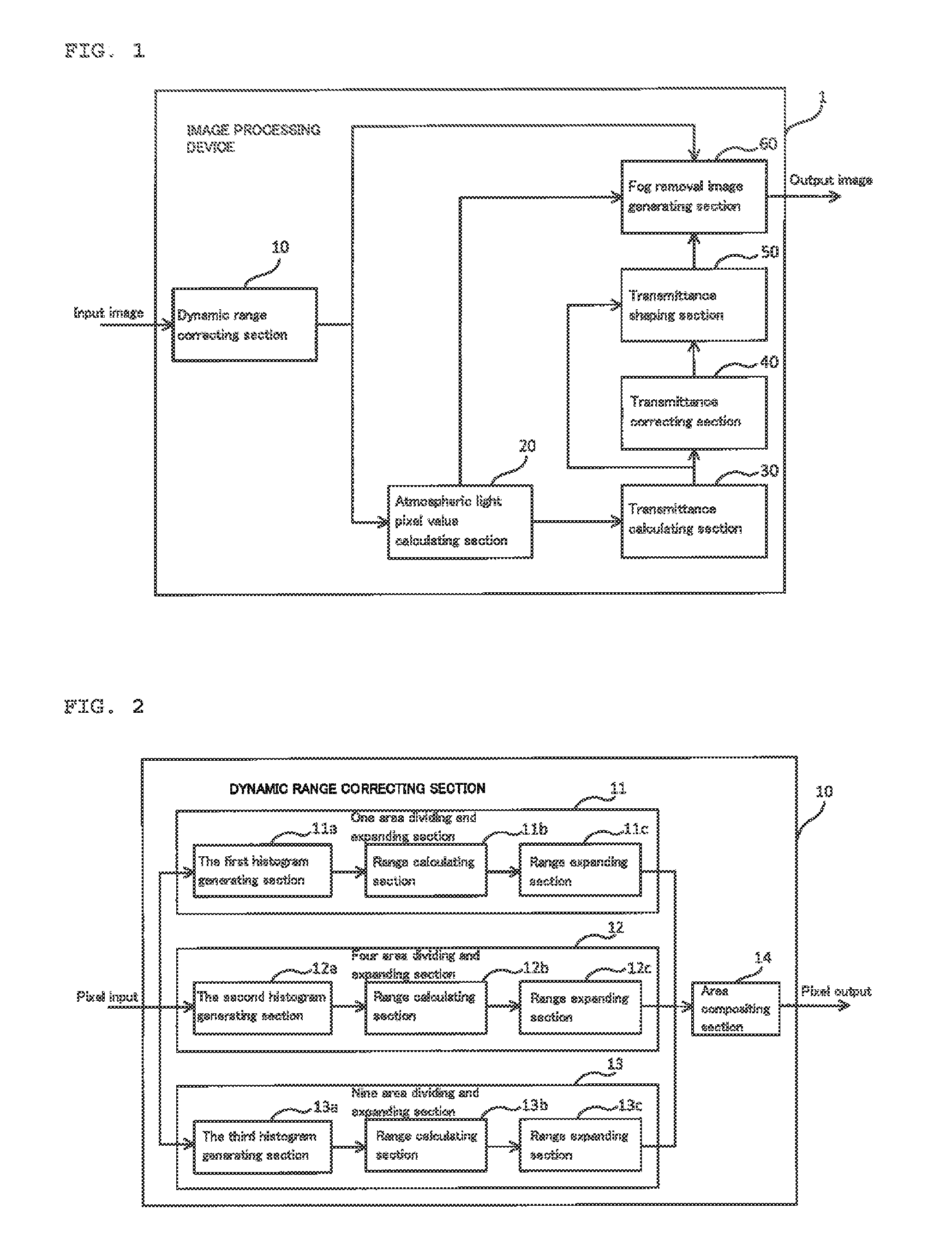
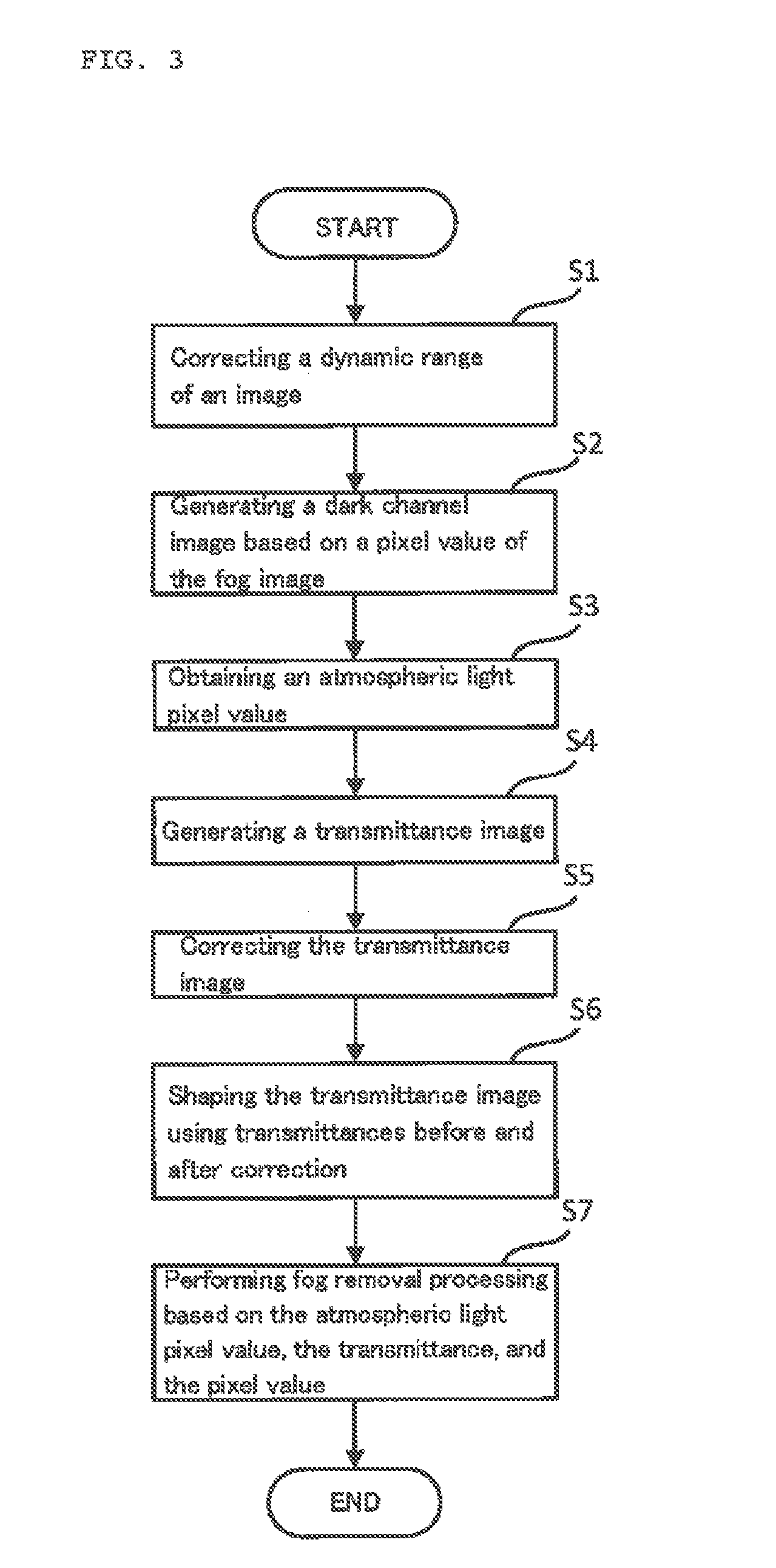
[0027]FIG. 1 is a block diagram illustrating a configuration of an image processing device 1 according to a first embodiment. The image processing device 1 illustrated in FIG. 1 is an device for performing a fog removal processing of an image as an image processing. The term “fog” indicates a phenomenon causing the low visibility due to small water particles floating in the air. “Fog” is also called as “mist” and “haze”. Not limited to fog, phenomena that make an object in an image hard to be seen due to particulates in the air are also included. Furthermore, the term “image” includes a still image and a moving image. As illustrated in FIG. 1, the image processing device 1 includes a dynamic range correcting section (a range correcting section) 10, an atmospheric light pixel value calculating section (a dark channel image generating section) 20, a transmittance calculating section (a transmittance image generating section) 30, a transmittance correcting section 40,...

second embodiment

A Second Embodiment

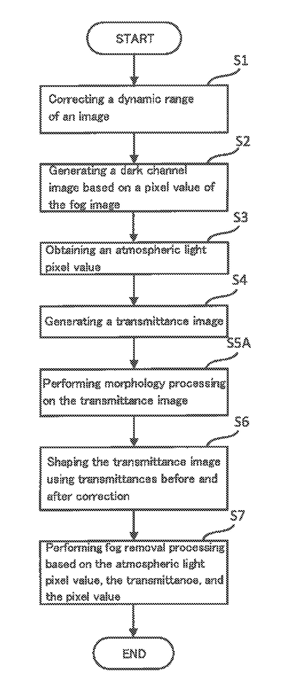
[0080]In the first embodiment described above, the transmittance correcting section 40 performs the transmittance correcting processing as illustrated in FIG. 7, meanwhile, a transmittance morphology processing section 40A performs a transmittance correcting processing (an expansion processing and a morphology processing) in the second embodiment.

[0081]FIG. 8 is a block diagram illustrating a configuration of an image processing device according to a second embodiment. An image processing device 1A illustrated in FIG. 8 includes a transmittance morphology processing section 40A instead of the transmittance correcting section 40 in the image processing device 1 illustrated in FIG. 1. The other configurations are similar to the configurations described for FIG. 1, therefore, repetitive descriptions are omitted.

[0082]The transmittance morphology processing section 40A performs a morphology processing on a transmittance image outputted from the transmittance calculati...


PUM


Abstract

A fog in an image is quickly removed with a small processing load,An image processing device includes a dark channel image generating section 20 for generating a dark channel image based on an input image, a transmittance image generating section 30 for generating a transmittance image based on the dark channel image generated in the dark channel image generating section 20 and a pixel value of atmospheric light, a transmittance correcting section 40 for correcting the transmittance image generated in the transmittance image generating section 30, and a fog removal image generating section 60 for removing fog in the input image based on the transmittance image corrected in the transmittance correcting section 40, the pixel value of atmospheric light, and the input image.

Description

FIELD OF THE INVENTION[0001]The present invention relates to an image processing device, an image processing method, and a control program for removing fog in an image.BACKGROUND OF THE INVENTION[0002]An image processing method for removing fog in an image is known, for example as described in non-patent document 1. In this image processing method, an image processing device corrects an input image by dividing the pixel value (R, G, and B) of each pixel of the input image by the pixel value (R, G, and B) of atmospheric light. In addition, the image processing device estimates a density of fog in the corrected input image using the minimum values of R, G, and. B in a local region called a dark channel. Then, the image processing device calculates a rough transmittance from the density of fog. Furthermore, the image processing device calculates an accurate transmittance using a method called soft matting. The image processing device removes fog in an image using this transmittance.[00...

Claims


Application Information

Patent Timeline
Patent Type & Authority Applications(United States)
IPC IPC(8): G06T5/00G06K9/46
CPCG06T5/00G06K9/4661G06K2009/4666G06K9/46G06T5/007H04N1/4092G06T5/40G06T2207/20016G06T5/90
Inventor KONDOU, TSUYOSHI
Owner NIPPON SYSTWARE
Learn More