Method and system for automated visual analysis of a dipstick using standard user equipment

a dipstick and user equipment technology, applied in the field of automatic visual analysis of dipsticks, can solve the problems of interpretation and misdiagnosis, and non-expert interpretation of dipsticks,

Active Publication Date: 2015-11-12
HEALTHY IO LTD
View PDF8 Cites 12 Cited by
  • Summary
  • Abstract
  • Description
  • Claims
  • Application Information

AI Technical Summary

Benefits of technology

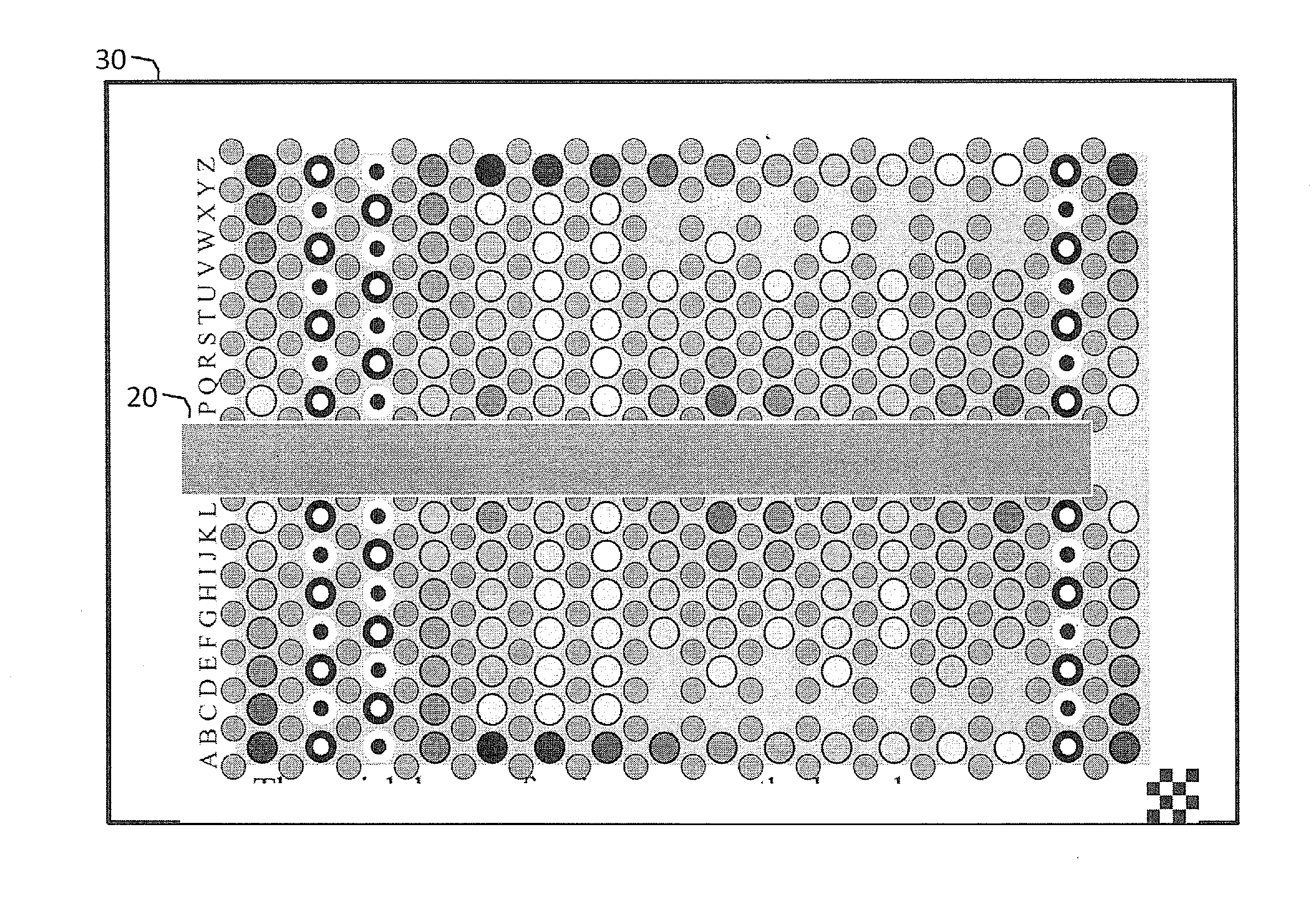
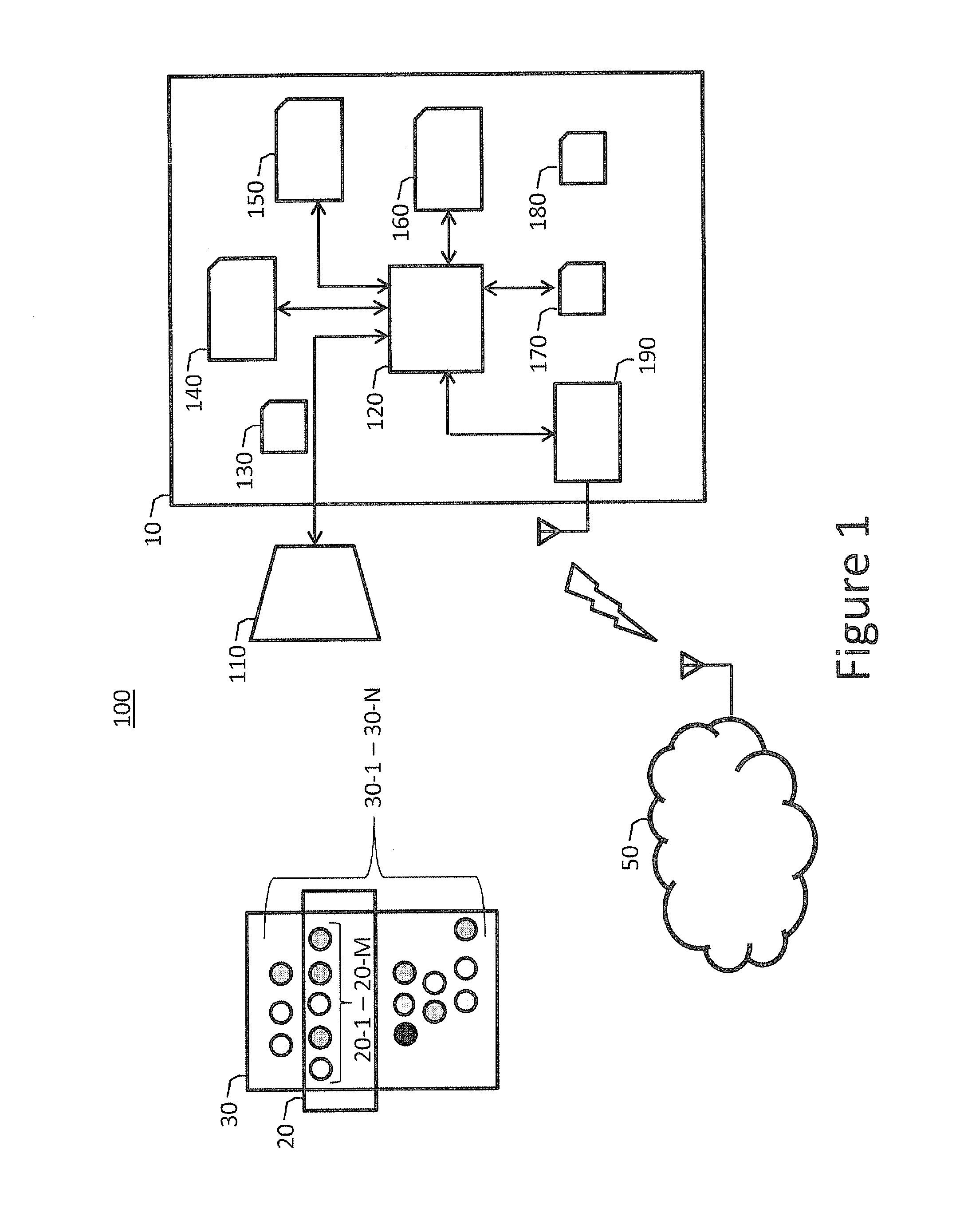
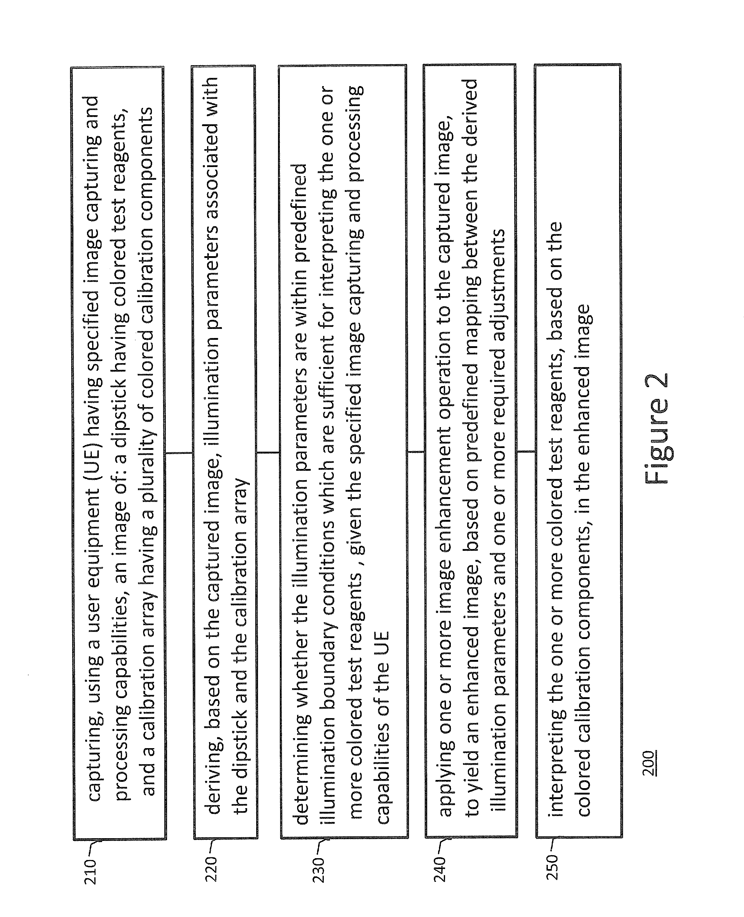
[0010]According to one embodiment of the present invention, there is provided a method of visual analysis of a dipstick using user equipment having optical capturing and image processing capabilities. The method may include the following steps: capturing, through a user equipment (UE) having specified image capturing and processing capabilities, an image of a dipstick having one or more colored test reagents, and a calibration array having a plurality of colored calibration elements, tailored specifically for the dipstick color reagents; deriving, based on the captured image, illumination parameters associated with the dipstick and the calibration array; determining whether the illumination parameters are within predefined illumination boundary conditions which are sufficient for interpreting the one or more colored test reagents, given the specified image capturing and processing capabilities of the UE; applying one or more image enhancement operations on the captured image, based on predefined mappings between the derived illumination parameters and one or more required adjustments; and interpreting the one or more colored test reagents, based on the colored calibration elements, in the enhanced captured image. Advantageously, by embodiments of the present invention, the dipstick-specific calibrator can, in real time, determine whether the environment of choice crosses boundary conditions.

Problems solved by technology

A non-expert interpretation of the dipstick is also not recommended—for the fear of wrong interpretation and misdiagnosis.

Method used


Image

  • Method and system for automated visual analysis of a dipstick using standard user equipment
  • Method and system for automated visual analysis of a dipstick using standard user equipment
  • Method and system for automated visual analysis of a dipstick using standard user equipment

Examples


Embodiment Construction

[0018]With specific reference now to the drawings in detail, it is stressed that the particulars shown are for the purpose of example and solely for discussing the preferred embodiments of the present invention, and are presented in the cause of providing what is believed to be the most useful and readily understood description of the principles and conceptual aspects of the invention. In this regard, no attempt is made to show structural details of the invention in more detail than is necessary for a fundamental understanding of the invention. The description taken with the drawings makes apparent to those skilled in the art how the several forms of the invention may be embodied in practice.

[0019]Before explaining the embodiments of the invention in detail, it is to be understood that the invention is not limited in its application to the details of construction and the arrangement of the components set forth in the following descriptions or illustrated in the drawings. The inventi...


PUM


Abstract

A method and system for automated visual analysis of a dipstick using standard user equipment (UE) are disclosed herein. The method may include the following steps: capturing, using an arbitrary UE having specified image capturing and processing capabilities, an image of a dipstick having colored test reagents, and a calibration array having a plurality of colored calibration elements which are tailored specifically to the test reagents; deriving, based on the captured image, illumination parameters associated with the dipstick and the calibration array; determining whether the illumination parameters are within predefined illumination boundary conditions sufficient for interpreting the test reagents, given the specified image capturing and processing capabilities of the UE; applying image enhancement operations to the captured image, based on predefined mapping between the derived illumination parameters and the required adjustments; and interpreting the colored test reagents, based on the colored calibration elements, in the enhanced captured image.

Description

FIELD OF THE INVENTION[0001]The present invention relates generally to systems and methods of automatically analyzing dipsticks, and in particular to such methods implementing image processing techniques tailored for standard user equipment.BACKGROUND OF THE INVENTION[0002]Prior to setting forth a short discussion of the related art, it may be helpful to set forth definitions of certain terms that will be used hereinafter.[0003]The term “user equipment” (UE) refers herein to any device used directly by an end-user to communicate. It can be a hand-held telephone, a laptop computer equipped with a mobile broadband adapter, or any other device. In the context used herein UE refers specifically to an arbitrary platform which is equipped with image capturing, image processing, and wireless communication capabilities.[0004]The term “testing dipstick” or simply “dipstick” refers herein to a testing measurement device usually made of paper or cardboard and is impregnated with reagents that ...

Claims


Application Information

Patent Timeline
Patent Type & Authority Applications(United States)
IPC IPC(8): G06T7/40G06K9/20G06T7/00G06K9/46G06V10/56
CPCG06T7/408G06K9/4652G06K9/2027G06T2207/30004G06T7/0012G06K2009/4666G06T2207/10024G06K9/4661G06T2207/30072G06T7/90G06T5/007G01N21/78G01N21/8483G06V10/56
Inventor ADIRI, YONATANOMER, IDOMENDELOWITZ, SHACHARSALOMON, ROEE
Owner HEALTHY IO LTD
Why Eureka
Try Eureka