
System, method and computer-accessible medium for depth of field imaging for three-dimensional sensing utilizing a spatial light modulator microscope arrangement

a technology of spatial light modulator and depth of field imaging, applied in the field of microscopy, can solve the problems of loss of signal, insufficient temporal or spatial resolution, lack of high frame rate three-dimensional imaging solutions,

Inactive Publication Date: 2015-11-12
THE TRUSTEES OF COLUMBIA UNIV IN THE CITY OF NEW YORK
View PDF5 Cites 30 Cited by
  • Summary
  • Abstract
  • Description
  • Claims
  • Application Information

AI Technical Summary

Benefits of technology

The patent describes a system that can generate an image of a sample by using a diffraction arrangement to modify the phase or amplitude of electro-magnetic radiation. The system can create an illumination pattern on the sample and then receive a return radiation from the sample that is based on the illumination pattern. An imaging arrangement can then generate an image based on the further radiation received from the wavefront modification arrangement. The system can make high-quality images that are not affected by defocus blur.

Problems solved by technology

However, common problems encountered with existing imaging and sensing methodologies can include a tendency for phototoxicity / photobleaching, insufficient temporal or spatial resolution, loss of signal when embedded in highly scattered materials, and a lack of high frame-rate three- dimensional imaging solutions.
However, currently there does not exist an optical solution for this type of imaging, although numerous techniques have attempted to achieve an optical solution.

Method used


Image

  • System, method and computer-accessible medium for depth of field imaging for three-dimensional sensing utilizing a spatial light modulator microscope arrangement
  • System, method and computer-accessible medium for depth of field imaging for three-dimensional sensing utilizing a spatial light modulator microscope arrangement
  • System, method and computer-accessible medium for depth of field imaging for three-dimensional sensing utilizing a spatial light modulator microscope arrangement

Examples


Embodiment Construction

[0007]These and other objects of the present disclosure can be achieved by provision of exemplary systems, methods and computer-accessible for generating at least one image of a portion(s) of a sample.

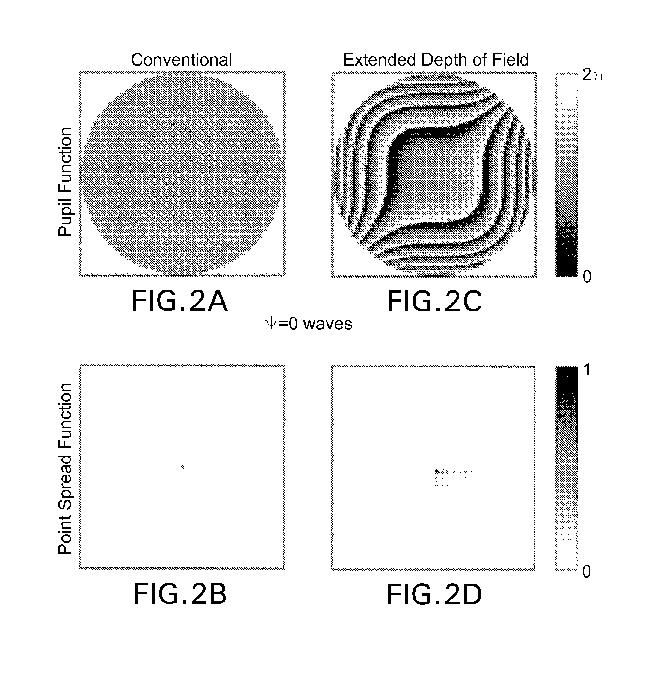
[0008]To that end, it is possible to provided systems, methods and computer-accessible medium which can utilize Spatial Light Modulator (SLM) microscopy that can customize the sample illumination pattern from the microscope to simultaneously interrogate multiple targets localized within the sample. An exemplary SLM microscope arrangement can be used to image target locations at, e.g., arbitrary 3D coordinate by using, e.g., an extended Depth-of-Field computational imaging system. Multi-site three-dimensional targeting and sensing can be used in both transparent and scattering media.

[0009]According to an exemplary embodiment of the present disclosure, the system, method and computer-accessible medium can utilize, e.g., a computer hardware arrangement. With such exemplary arrangement, it...


PUM


Abstract

Spatial Light Modulator (SLM) microscopy can customize a sample illumination pattern from the microscope to simultaneously interrogate multiple targets localized within the sample. An exemplary SLM microscope arrangement can be used to image target locations at, e.g., arbitrary 3D coordinate by using, e.g., an extended Depth-of-Field computational imaging system. Multi-site three-dimensional targeting and sensing can be used in both transparent and scattering media. To that end, exemplary embodiments of system, method and computer-accessible medium can be provided for generating at least one image of at least one portion of a sample. For example, a computer hardware arrangement corn be provided. Such exemplary arrangement can be configured to receive information related to light, modified by the sample, after being previously manipulated by a optical addressing (e.g., diffraction) arrangement. Such exemplary computer hardware arrangement can also generate the image(s) based on the information.

Description

CROSS-REFERENCE TO RELATED APPLICATION(S)[0001]The present application relates to and claim priority from U.S. patent application Ser. No. 61 / 756,803 filed on Jan. 25, 2013, and U.S. Patent Application Ser. No. 61 / 798,747 filed on Mar. 15, 2013, the entire disclosures of which are incorporated herein by reference.FIELD OF THE DISCLOSURE[0002]The present disclosure relates generally to microscopy, and more specifically, to exemplary systems, methods and computer-accessible mediums for extended depth of field (“DOF”) imaging utilizing structured light illumination.BACKGROUND INFORMATION[0003]Due to a growing variety of molecular probes, dynamic measurements of the functional characteristics from a localized environment in biological systems can be encoded into the temporal modulation of an optical signal. Examples can include fluorescence encoding of action potentials from neurons in calcium imaging (See, e.g., References 1 and 2), Ph sensitivity (See, e.g., Reference 3) and voltage s...

Claims


Application Information

Patent Timeline
IPC IPC(8): G02B27/00G06K9/00G02B21/36G02B21/00G01N21/64G02B21/06
CPCG02B27/0075G01N21/6458G02B21/06G02B21/367G02B21/0032G06K9/00134G02B21/365G02B21/0076G02B26/06G06V20/693
Inventor YUSTE, RAFAELQUIRIN, SEAN ALBERTPETERKA, DARCY S.
Owner THE TRUSTEES OF COLUMBIA UNIV IN THE CITY OF NEW YORK
Learn More