
Starting device

a technology of starting device and guide roller, which is applied in the direction of fluid coupling, rotary clutch, gearing, etc., can solve the problems of pendulum (mass body) exhibiting unstable behavior, suppress abnormal sound generation, and favorably maintain the function of the cushioning member

Inactive Publication Date: 2015-11-12
AISIN AW CO LTD
View PDF3 Cites 12 Cited by
  • Summary
  • Abstract
  • Description
  • Claims
  • Application Information

AI Technical Summary

Benefits of technology

The invention is a starting device that includes a centrifugal-pendulum vibration absorbing device. The device stabilizes the behavior of mass bodies when the support member of the device rotates at a low speed. The device includes a protrusion that helps stabilize the mass bodies and prevents abnormal sounds and movement. The protrusion can be easily formed and the configuration of the device is simplified. The device also includes a thrust force that helps keep the mass bodies in place when the lock-up clutch is disengaged. Overall, the invention provides a simple and effective solution to stabilize the behavior of mass bodies in a starting device.

Problems solved by technology

In the starting device described in Patent Document 1, however, in the case where the lock-up clutch is disengaged, the pendulum (mass body) may exhibit unstable behavior such as a tilt relative to the axis of the flange of the centrifugal-pendulum vibration absorbing device and a shake relative to the flange immediately after rotation of the flange is started and immediately before such rotation is stopped, that is, when the flange rotates at a significantly low rotational speed even if the flow of the working fluid in the clutch engagement chamber is gentle, and the pendulum may collide against the flange to generate abnormal sound.

Method used


Image

  • Starting device
  • Starting device
  • Starting device

Examples


Embodiment Construction

[0036]Now, an exemplary embodiment will be described with reference to the drawings.

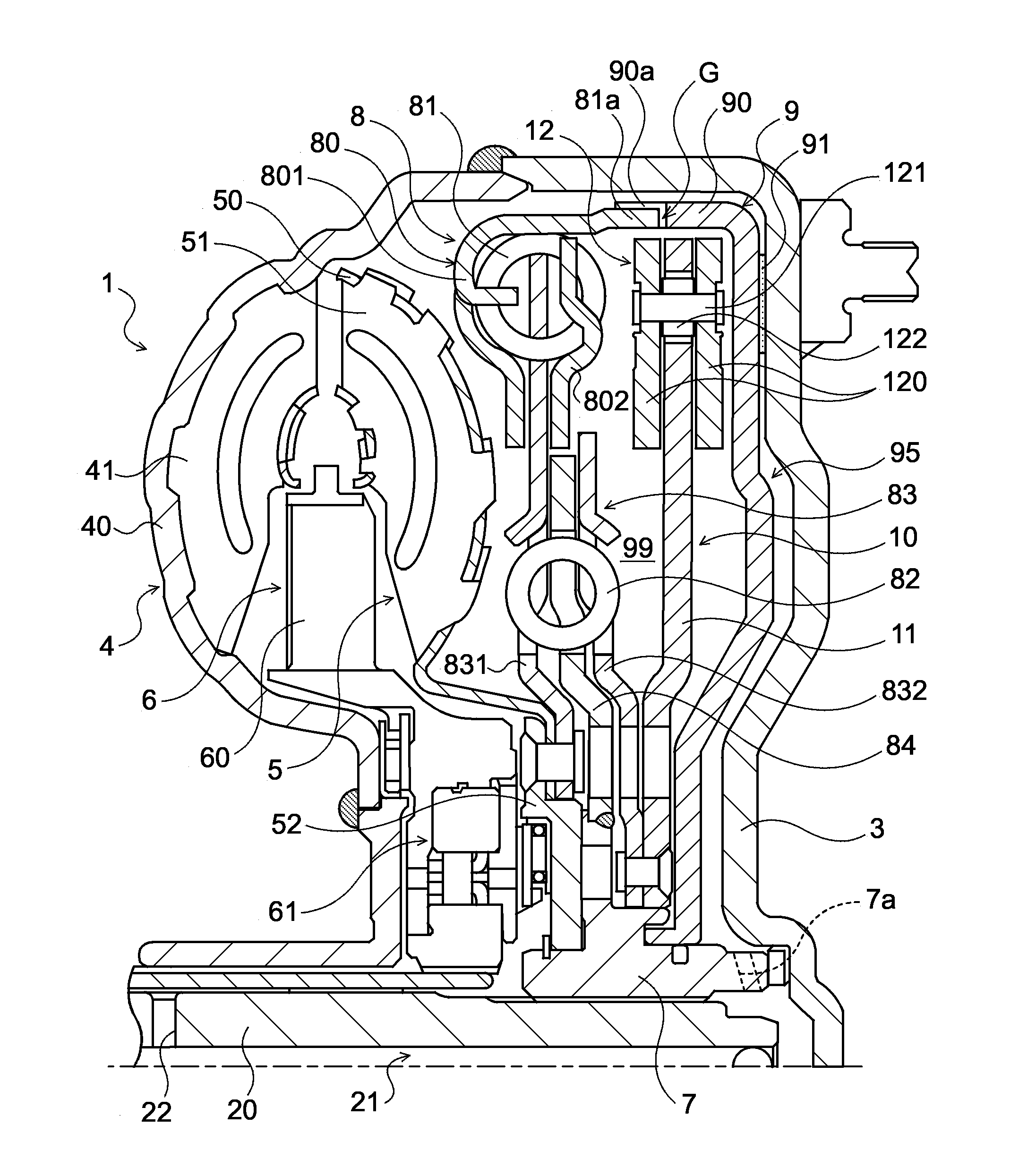
[0037]FIG. 1 is a schematic diagram illustrating the configuration of a starting device 1 according to an exemplary embodiment. The starting device 1 illustrated in the drawing is mounted on a vehicle including an engine (internal combustion engine) serving as a motor, and transmits power from the engine to a speed change device (not illustrated) that is an automatic transmission (AT) or a continuously variable transmission (CVT). The starting device 1 includes a front cover (input member) 3 coupled to a crankshaft of the engine, a pump impeller (input-side fluid transmission element) 4 joined to the front cover 3, a turbine runner (output-side fluid transmission element) 5 disposed to face the pump impeller 4 and coupled to an input shaft 20 of the speed change device, a stator 6 that adjusts a flow of working oil (working fluid) from the turbine runner 5 to the pump impeller 4, a damper hub (output...


PUM


Abstract

In a starting device including a centrifugal-pendulum vibration absorbing device, while lock-up is released, a flow of working oil directed from a lock-up piston side toward a damper mechanism is produced in a clutch engagement chamber. A thrust force in the axial direction directed from the lock-up piston toward the damper mechanism is applied to a weight, of a mass body of the centrifugal-pendulum vibration absorbing device, disposed on the lock-up piston side. A support member of the centrifugal-pendulum vibration absorbing device is provided with weight support protrusions that project in the axial direction of an input shaft of a speed change device toward the weight disposed on the lock-up piston side.

Description

TECHNICAL FIELD[0001]An embodiment is described that relates to a starting device including, for example, a centrifugal-pendulum vibration absorbing device.BACKGROUND ART[0002]Hitherto, there has been known a starting device including a pump impeller, a turbine runner, a lock-up clutch, a spring damper mechanism, and so forth in addition to a centrifugal-pendulum damper (centrifugal-pendulum vibration absorbing device) having a flange (support member) and a pendulum (mass body) (see Patent Document 1, for example). In the starting device, a piston of the lock-up clutch and a front cover define a clutch disengagement chamber to which a clutch disengagement pressure is supplied. In addition, the piston of the lock-up clutch is coupled to an input element of the damper mechanism, and the piston and the input element define a clutch engagement chamber to which a clutch engagement pressure regulated independently of the clutch disengagement pressure is supplied. The centrifugal-pendulum ...

Claims


Application Information

Patent Timeline
Patent Type & Authority Applications(United States)
IPC IPC(8): F16F15/14F16H45/02
CPCF16F15/145F16H45/02F16H2045/0294F16H2045/0226F16H2045/0205F16H2045/0263
Inventor TAKIKAWA, YOSHIHIRONAGAE, AKIHIROMARUYAMA, KAZUTO
Owner AISIN AW CO LTD
Learn More