
Liquid crystal display apparatus

Inactive Publication Date: 2015-10-22
SHARP KK
View PDF2 Cites 4 Cited by
  • Summary
  • Abstract
  • Description
  • Claims
  • Application Information

AI Technical Summary

Benefits of technology

The present invention aims to provide a liquid crystal display apparatus that can facilitate narrowing the frame and fix different members while allowing for variations in their thickness. This allows for a more compact and flexible design.

Problems solved by technology

However, on the other hand, the liquid crystal display apparatuses including the bezel still continue to be produced due to existing production facilities, costs and the like.
In order to reduce the variations in the entire thickness of the respective members, when the respective members are fixed by a strong force in the front-back direction using the four bar-shaped frame members, distortions, wrinkles, or the like occur in the liquid crystal panel and the optical sheet, such that image quality may be deteriorated.
On the other hand, when the respective members are fixed by a weak force in the front-back direction using bar-shaped frame members having a wide interval between portions which pinch the respective members, rattling occurs in the respective members, whereby assembly failure occurs in the liquid crystal display apparatus.

Method used


Image

  • Liquid crystal display apparatus
  • Liquid crystal display apparatus
  • Liquid crystal display apparatus

Examples


embodiment 1

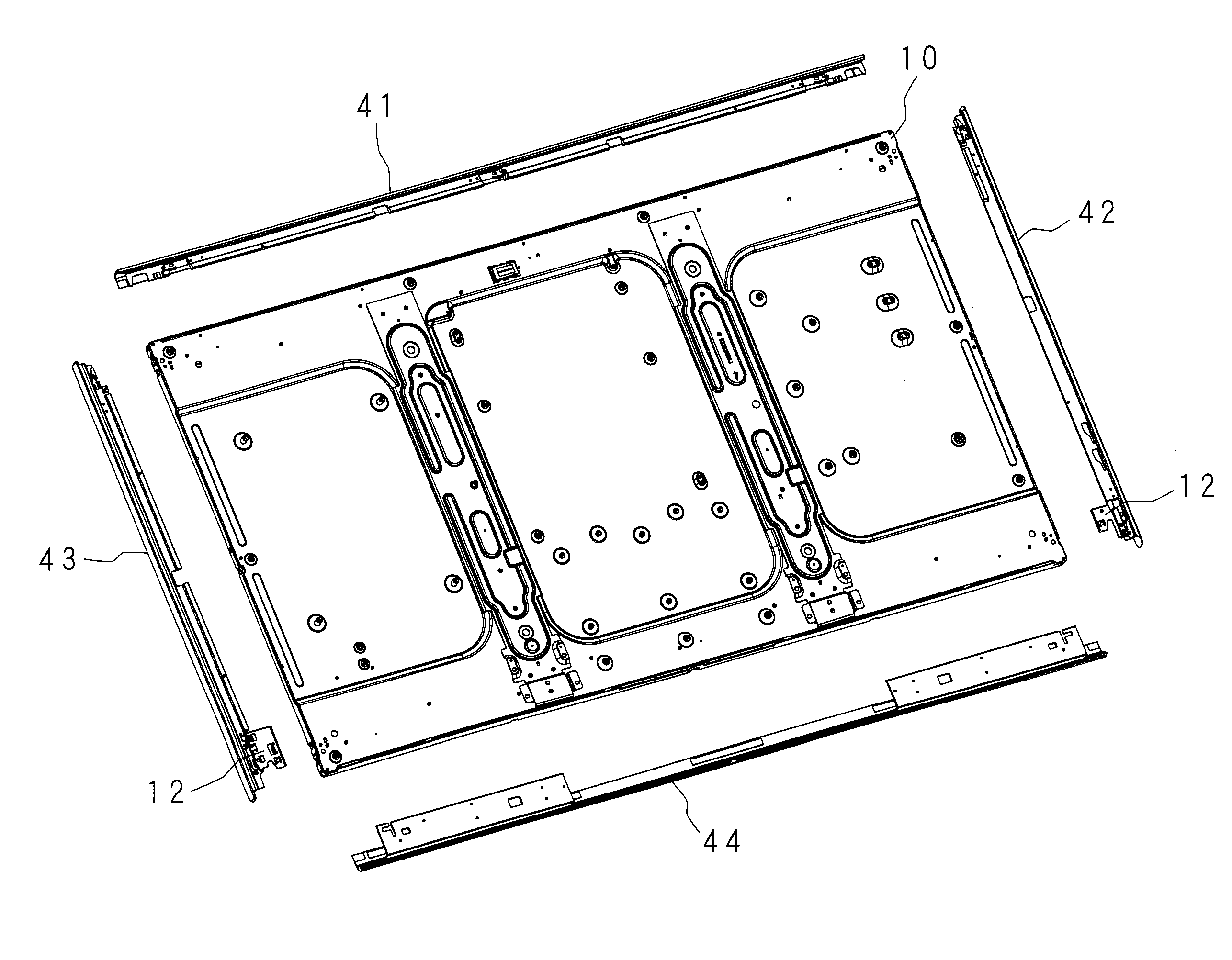
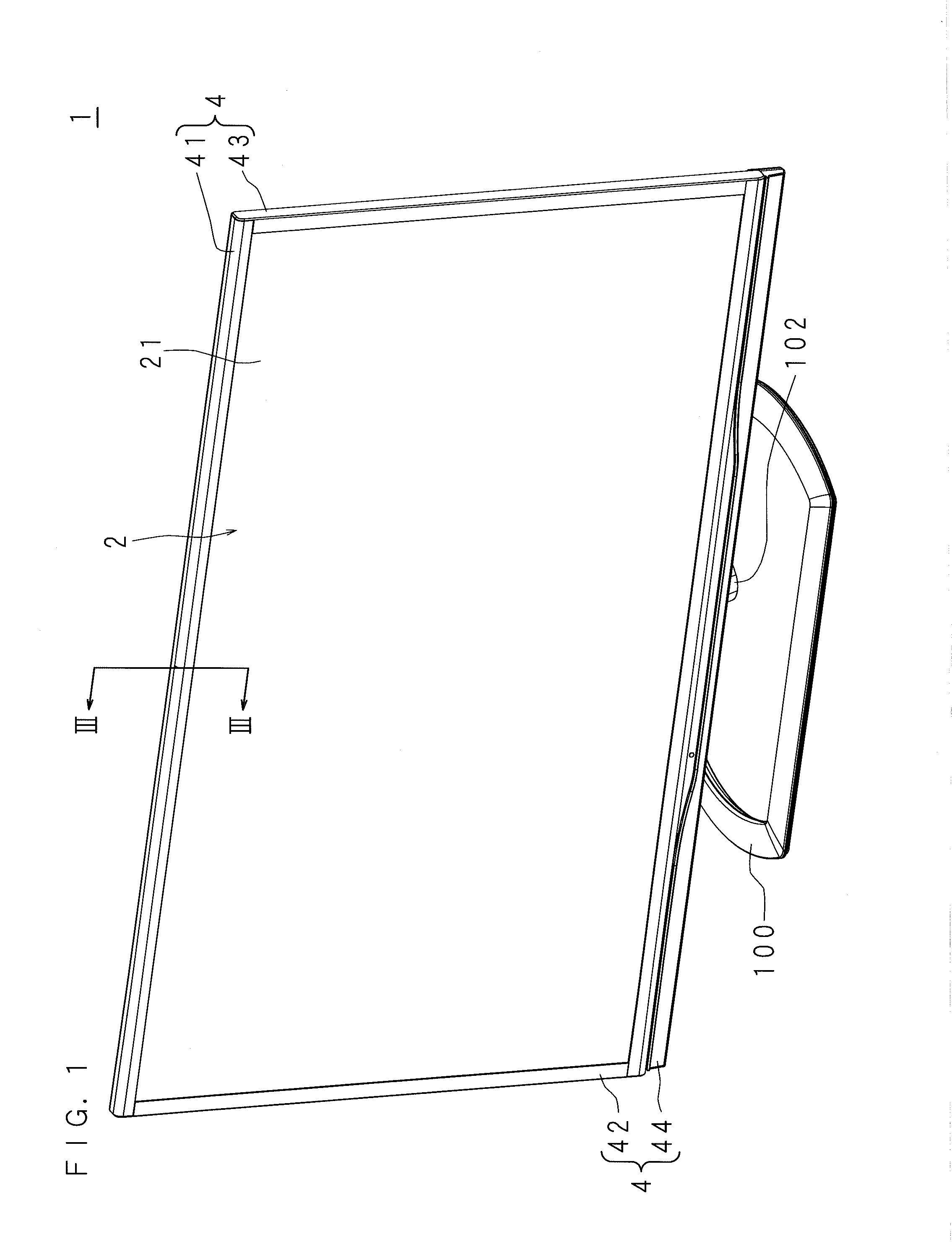
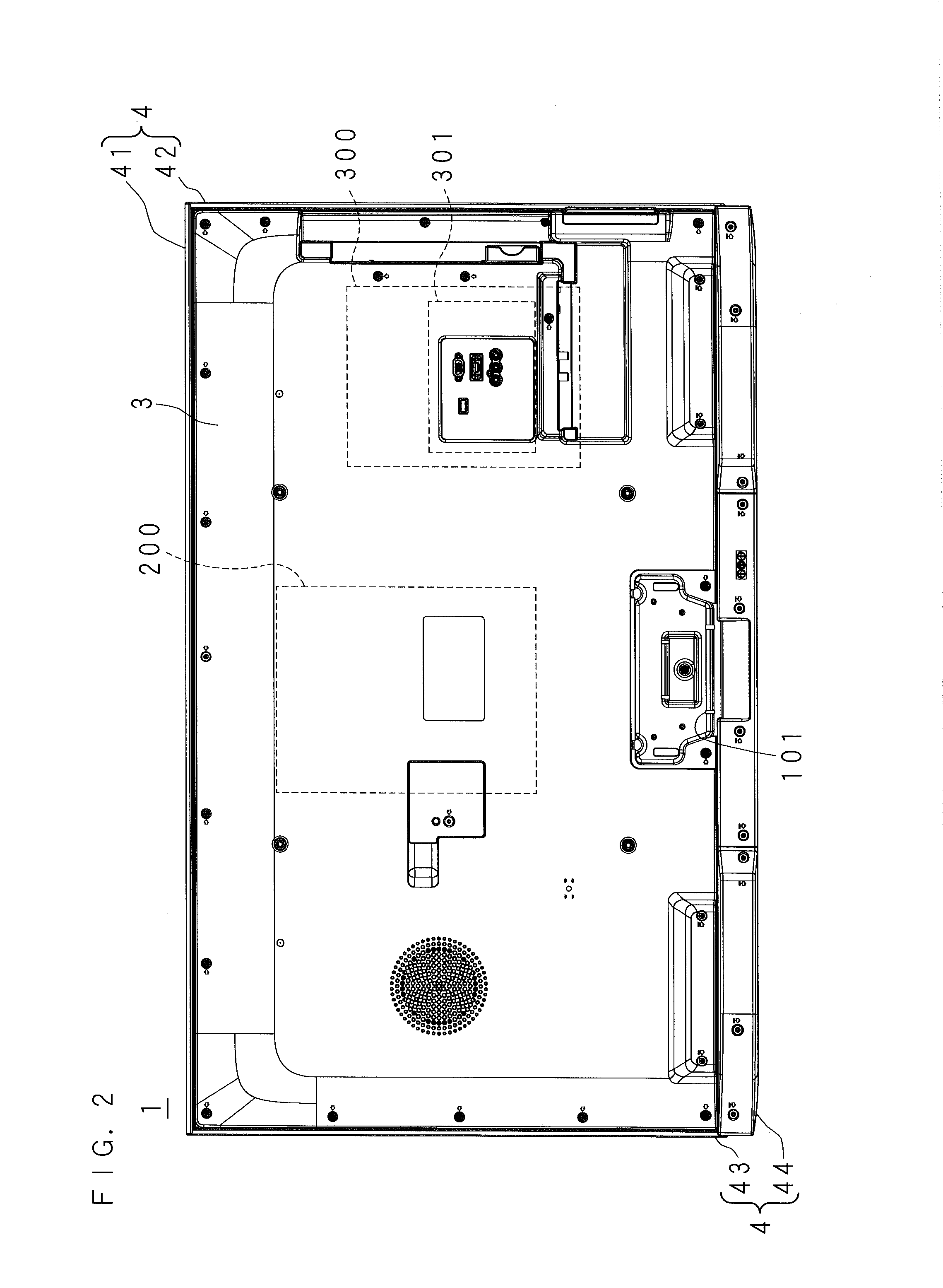
[0083]FIG. 1 is a perspective view of a television receiver 1 seen from a front side thereof. FIG. 2 is a rear view of the television receiver 1. Herein, when a viewer faces a screen 21 of the television receiver 1 in an upright state that displays an image, the viewer side of the screen 21 will be referred to as a front side, and the opposite side thereof will be referred to as a rear side or a back side. The screen 21 has a laterally long rectangular shape. When a viewer sees the screen 21, the right side of the screen 21 in a long side direction (a lateral direction) thereof will be referred to as right of the television receiver 1, and the left side of the screen 21 in the long side direction thereof will be referred to as left of the television receiver 1. Further, the upper side of the screen 21 in a short side direction (a vertical direction) thereof will be referred to as top of the television receiver 1, and the lower side of the screen 21 in the short side direction thereo...

embodiment 2

[0176]Embodiment 2 relates to a configuration in which the leaf spring 47 is fixed to the upper frame 41 and the side frames 42 and 43 by the screws.

[0177]In Embodiment 1, the joint region of the leaf spring 47 and the respective inner surfaces of the upper frame 41 and the side frames 42 and 43 are jointed by caulking using a rivet, etc., for example. In Embodiment 2, the joint region of the leaf spring 47 and the respective outer surfaces of the upper frame 41 and the side frames 42 and 43 are jointed by screws.

[0178]The same parts of the configuration according to Embodiment 2 as those in Embodiment 1 will be denoted by the same reference numerals, and will not be described in detail.

[0179]FIG. 13 is a partial enlarged view of a left upper portion of the liquid crystal module 10, and a part of each of the upper frame 41 and the side frame 43, seen from the rear side.

[0180]The leaf springs 47 are fixed to the respective rear portions of the upper frame 41 and the side frames 42 an...


PUM


Abstract

The liquid crystal display apparatus includes a liquid crystal module that has: a liquid crystal panel, an optical sheet, a backlight, and a box-shaped housing which has an opening on its front side and houses at least the optical sheet and the backlight, which are sequentially laminated from a front side to a rear side; and a frame-shaped member that covers peripheral surface sides of the liquid crystal panel and the housing. The liquid crystal display apparatus further includes: a frame body that extends along a peripheral edge of the liquid crystal module, have a cross section orthogonal to an extending direction formed in a U-shape opened toward the liquid crystal module, and is partially in contact with the housing and the frame-shaped member to hold the liquid crystal module; and a leaf spring that is installed at a portion where a rear surface of the housing and the frame body face each other, and presses the housing and the frame body so as to be separated from each other in the thickness direction of the housing.

Description

CROSS-REFERENCE TO RELATED APPLICATION[0001]This application is the national phase under 35 U.S.C. §371 of PCT International Application No. PCT / JP2013 / 082018 which has an International filing date of Nov. 28, 2013 and designated the United States of America, which claims priority under 35 U.S.C. 119(a) to Patent Application Nos. 2012-261293 and 2013-067253, filed in Japan on Nov. 29, 2012 and Mar. 27, 2013, all of which are hereby expressly incorporated by reference into the present application.BACKGROUND[0002]1. Technical Field[0003]The present invention relates to a liquid crystal display apparatus.[0004]2. Description of Related Art[0005]In a liquid crystal display apparatus, respective members such as a liquid crystal panel, an optical sheet, and the like, which are laminated in a front-back direction, are supported by a bezel located at a peripheral edge thereof. By eliminating the bezel from the liquid crystal display apparatus, narrowing of a frame in the liquid crystal disp...

Claims


Application Information

Patent Timeline
IPC IPC(8): G02F1/1333
CPCG02F1/133308G02F2201/465G02F1/13332G02F1/133328
Inventor NOGUCHI, YOSHIHISA
Owner SHARP KK
Learn More