
Stereoscopic lens for digital cameras

a technology of stereoscopic lenses and digital cameras, applied in the field of stereoscopic lenses, can solve the problems of affecting the effect of the image quality of the image, the inconvenience of the majority of people, and the inability to achieve the effect of achieving the effect of reducing the difficulty of focusing

Inactive Publication Date: 2015-10-22
LIPTON LENNY +1
View PDF7 Cites 10 Cited by
  • Summary
  • Abstract
  • Description
  • Claims
  • Application Information

AI Technical Summary

Benefits of technology

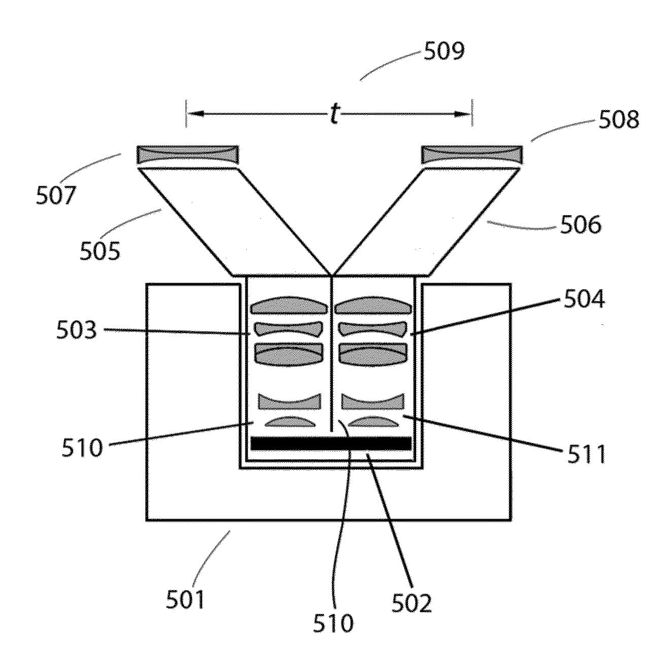
The present invention relates to a stereoscopic lens for digital cameras that can be used to capture theatrical stereoscopic motion pictures in 3D at the time of photography. The lens is designed to overcome the limitations of current beamsplitter rigs, which are bulky and require additional crewmembers for operation. The invention allows for easier and more flexible photography of stereoscopic motion pictures, reducing the cost and discomfort for actors and crew. The use of modern digital cinema cameras with greater light sensitivity and flexibility in blocking has led to a change in the style and working methods of shooting motion pictures, making photography simpler and more accessible. The invention also addresses the issue of asymmetries in stereoscopic images produced by beamsplitter rigs, which can cause viewer discomfort. Overall, the invention provides a more efficient and effective solution for capturing theatrical stereoscopic motion pictures in 3D.

Problems solved by technology

The art of three-dimensional cinematography has been held back because of the lack of a convenient means to photograph theatrical stereoscopic motion pictures.
This is called divergence because fusion of such image points requires the eyes' lens axes to diverge, rather than converge, and this may be uncomfortable for most people.
By such means it is possible to greatly reduce the effective interaxial separation.
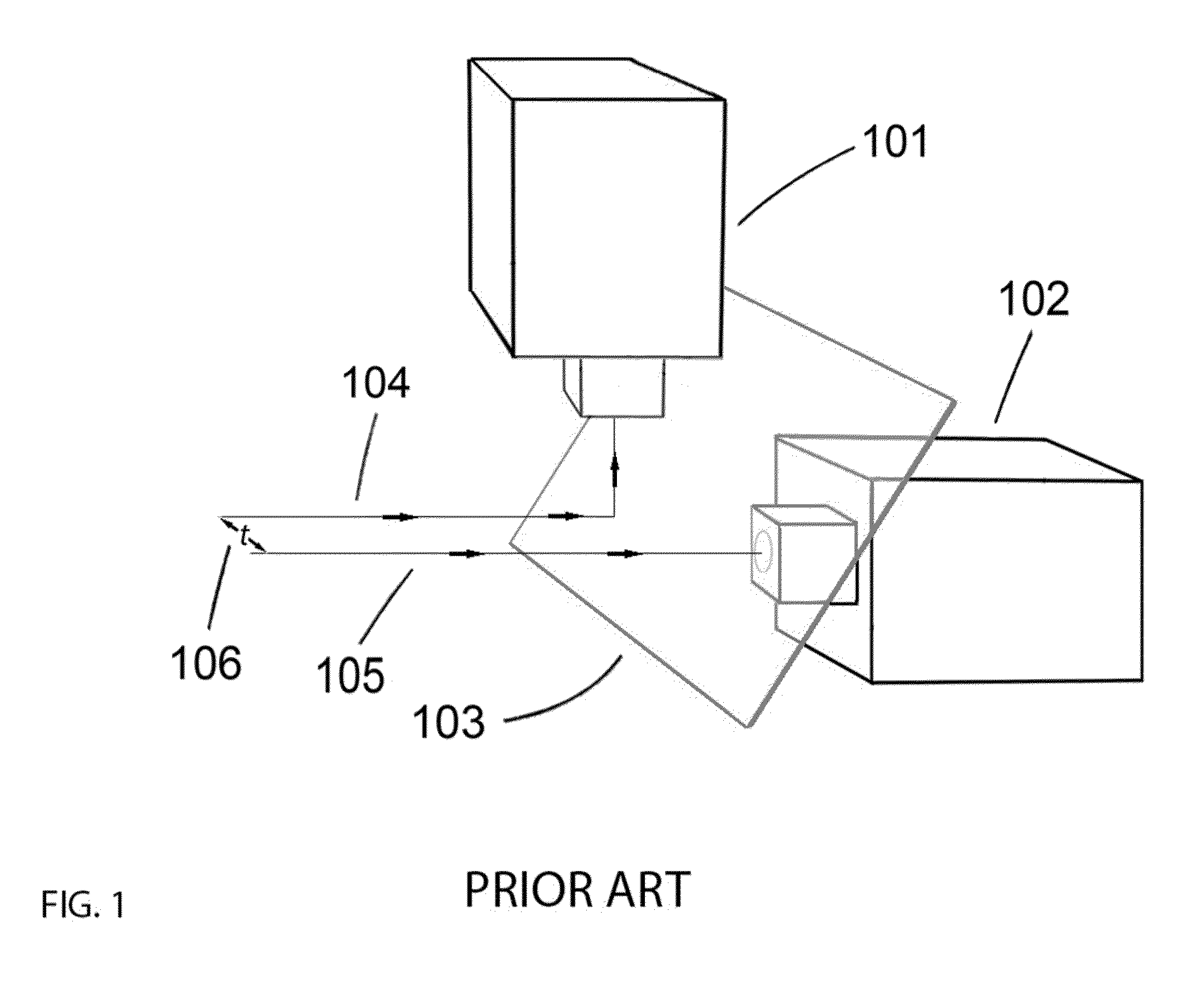
Although some of these rigs, in their latest incarnation, more or less eliminate the difficulties associated with the older versions of the product, they remain big and bulky and require additional crewmembers for operation as well as repeated calibration on set.
Stereoscopic images with asymmetries can cause viewer discomfort.
Beamsplitter rigs are especially prone to producing illumination (density and color) asymmetries and geometrical asymmetries.
The rigs, because of their bulk and weight, are mostly used for costly so-called tentpole productions whose budgets are in excess of $100 million.
Productions like these cannot afford the process of conversion or the budget or endure the rigors that are entailed when using rigs.

Method used


Image

  • Stereoscopic lens for digital cameras
  • Stereoscopic lens for digital cameras
  • Stereoscopic lens for digital cameras

Examples


Embodiment Construction

[0025]The present design seeks to provide an optical solution alternative to the rigs and to conversion in order by using a single unmodified digital camera for 3D cinematography.

[0026]In the past attempts to solve the problem of stereoscopic cinematography using a single camera for theatrical motion picture work has been attempted by a number of inventors such as Condon (U.S. Pat No. 4,464,028), Hoch (U.S. Pat. No. 3,825,328, and Bielusici (U.S. Pat No. 3,551,036). These efforts are prior to the advent of the digital cinema and therefore could not take advantages of that technology. The current design takes advantage of changes to filmmaking technology principally in two ways: the lens mount system used for modern digital cinema cameras is more or less the same as that which was used for cinematography using 35 mm film and reflex motion picture cameras, but for modern digital cameras there is no mirror reflex system and therefore the area from the lens mount itself to the image sen...


PUM


Abstract

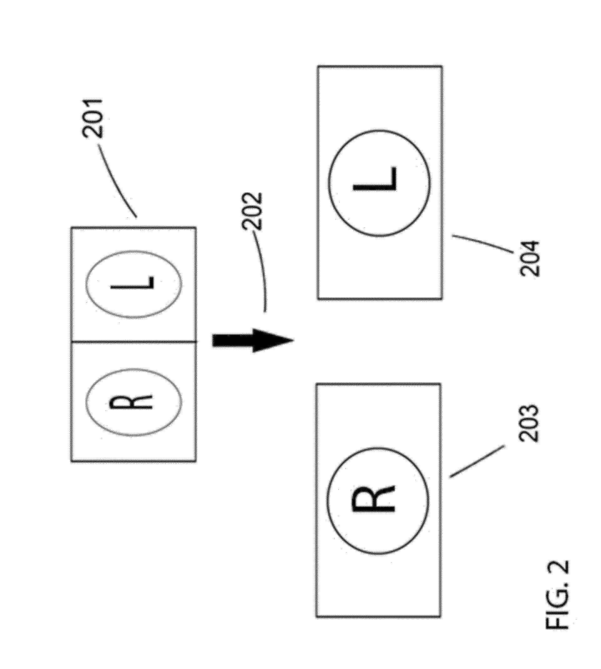
An apparatus is disclosed, the apparatus including a lens body configured to fit within a standard cinematic movie camera, the lens body including a plurality of optical elements including a plurality of lenses and a sensor. The plurality of optical elements is arranged to receive two channels of visual images and provide the two channels of images to the sensor.

Description

[0001]This application claims the benefit of U.S. Provisional Patent Application Ser. No. 61 / 981,833, filed Apr. 20, 2014, entitled “Stereoscopic Lens for Digital Cameras,” the entirety of which is incorporated herein by reference.BACKGROUND OF THE INVENTION[0002]1. Field of the Invention[0003]The present invention relates generally to the art of stereoscopic lenses for standard digital cinema cameras, and more specifically to digital cinema cameras enabling viewing cinematography in 3D at the time of photography using currently available digital cameras.[0004]2. Description of the Related Art[0005]The art of three-dimensional cinematography has been held back because of the lack of a convenient means to photograph theatrical stereoscopic motion pictures. There is no stereoscopic lens in general use that is used with a cinema quality digital camera to produce industry standard high quality images.[0006]Two methods are currently used for creating live-action stereoscopic motion pictu...

Claims


Application Information

Patent Timeline
IPC IPC(8): G02B13/00H04N5/225H04N13/02
CPCG02B13/0015H04N5/2254H04N13/02G03B17/565G03B35/10H04N13/161H04N13/178
Inventor LIPTON, LENNYRUPKALVIS, JOHN A.
Owner LIPTON LENNY
Learn More