
Mobile communication base station and method for allocating resources outside of a virtual carrier based on ue capabilities

a mobile communication base station and capability technology, applied in the direction of transmission path division, machine-to-machine/machine-type communication services, wireless commuication services, etc., to achieve the effect of reducing bandwidth, reducing congestion, and increasing the capacity of virtual carriers

Active Publication Date: 2015-10-15
SONY CORP
View PDF2 Cites 39 Cited by
  • Summary
  • Abstract
  • Description
  • Claims
  • Application Information

AI Technical Summary

Benefits of technology

This patent relates to increasing the capacity of a mobile network by allocating communication resources to devices based on their capabilities. By providing a wireless access interface that allows devices to inform the network of their capabilities, the network can allocate resources for devices with different capabilities, reducing congestion on the main frequency. This allows devices to communicate outside the virtual carrier provided by the network, increasing the overall capacity of the network.

Problems solved by technology

Since the number of devices may be relatively large, a technical problem exists because the number of communications devices wishing to communicate via the virtual carrier may produce congestion on, for example, a control channel or shared communications resources which are provided within the virtual carrier.

Method used


Image

  • Mobile communication base station and method for allocating resources outside of a virtual carrier based on ue capabilities
  • Mobile communication base station and method for allocating resources outside of a virtual carrier based on ue capabilities
  • Mobile communication base station and method for allocating resources outside of a virtual carrier based on ue capabilities

Examples


example network

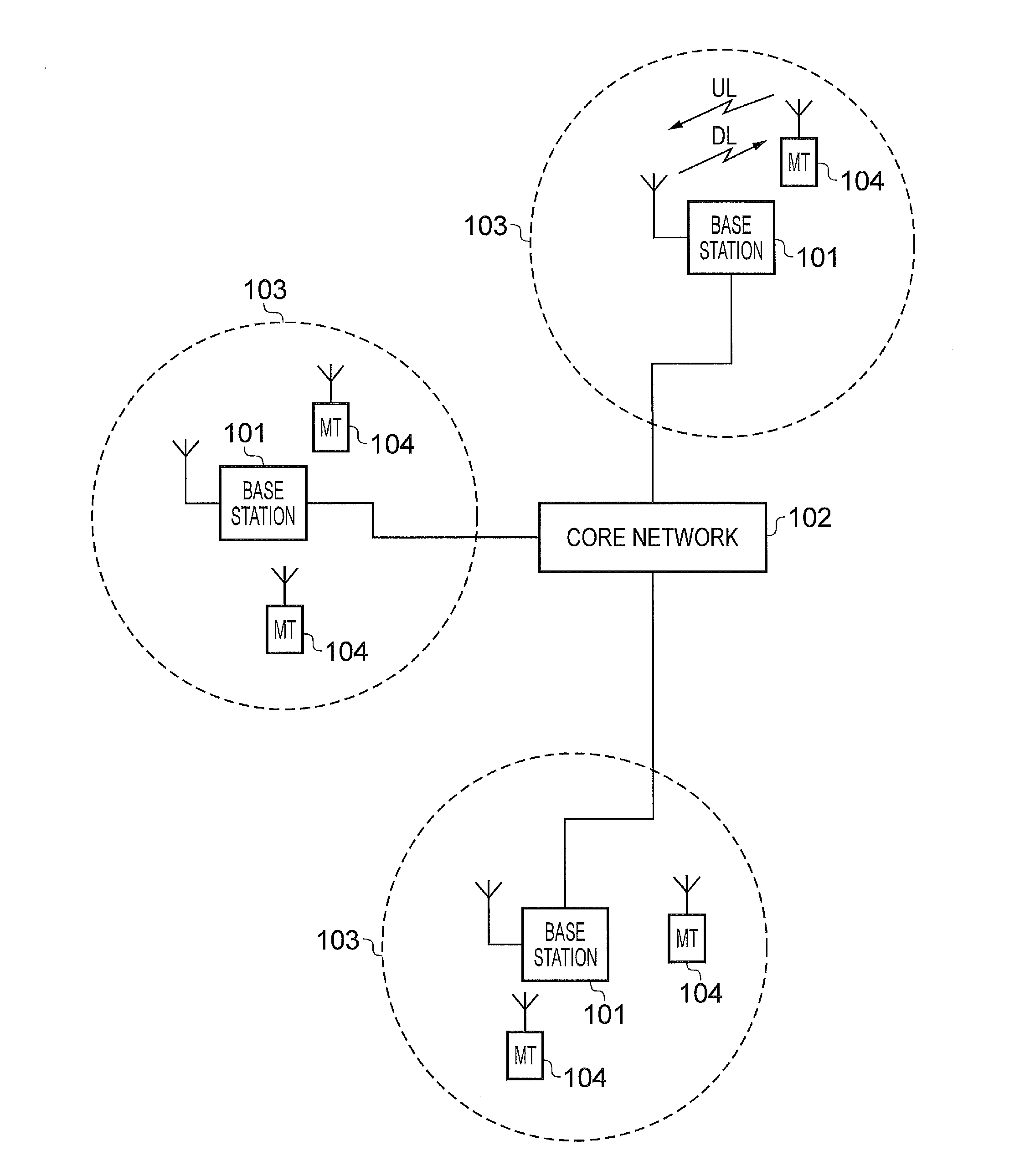
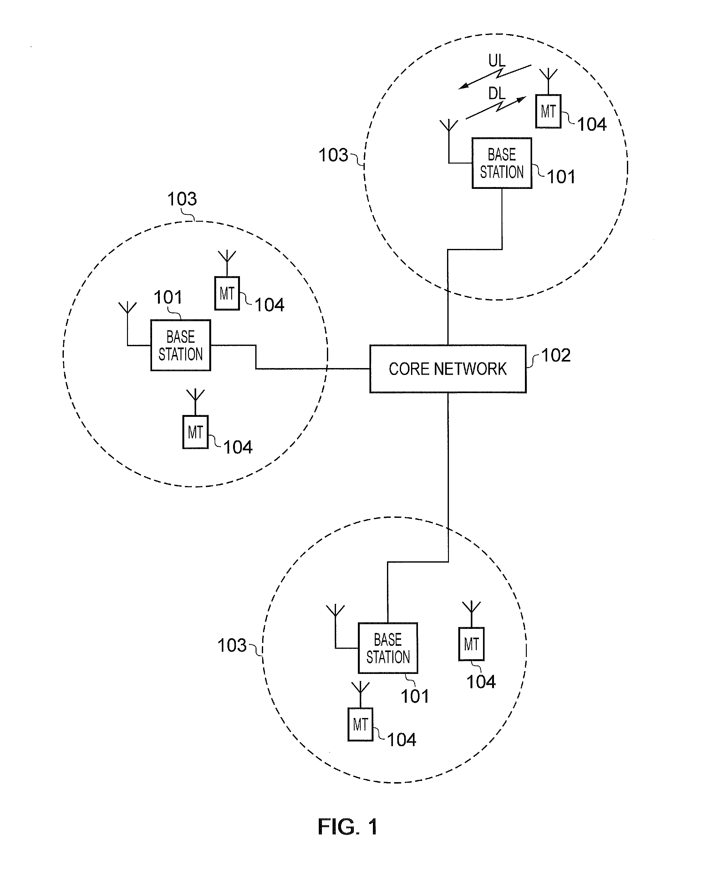
[0031]FIG. 1 provides a schematic diagram illustrating the basic functionality of a conventional mobile communications system.

[0032]The network includes a plurality of base stations 101 connected to a core network 102. Each base station provides a coverage area 103 (i.e. a cell) within which data can be communicated to and from communications devices 104. Data is transmitted from a base station 101 to a communications device 104 within a coverage area 103 via a radio downlink Data is transmitted from a communications device 104 to a base station 101 via a radio uplink The core network 102 routes data to and from the base stations 104 and provides functions such as authentication, mobility management, charging and so on.

[0033]The term communications devices will be used to refer to a communications terminal or apparatus which can transmit or receive data via the mobile communications system. Other terms may also be used for communications devices such as personal computing apparatus,...


PUM


Abstract

A mobile communications network includes one or more network elements providing a wireless access interface for communications devices. The wireless access interface provides plural communications resource elements across a host frequency bandwidth, and includes, within the host frequency bandwidth, first communications resource elements within a first frequency bandwidth for allocation preferably to reduced capability devices to receive signals representing the data transmitted by the transmitter unit within the first bandwidth forming a first virtual carrier, the reduced capability devices each having a receiver bandwidth which is greater than or equal to the first frequency bandwidth but less than the host frequency bandwidth. Communications devices of different capabilities can be allocated communications resources within different frequency ranges according to their capability, which can relieve congestion on a centre frequency of communications resources in which communications devices with a minimum bandwidth capability must receive communications resources for receiving down link signals.

Description

TECHNICAL FIELD OF THE DISCLOSURE[0001]The present disclosure relates to infrastructure equipment for mobile communications networks, mobile communications networks and systems and methods of communicating using mobile communications networks.BACKGROUND OF THE DISCLOSURE[0002]Mobile communications systems continue to be developed to provide wireless communications services to a greater variety of electronic devices. In more recent years, third and fourth generation mobile telecommunication systems, such as those based on the 3GPP defined UMTS and Long Term Evolution (LTE) architectures have been developed to support more sophisticated communications services to personal computing and communications devices than simple voice and messaging services offered by previous generations of mobile telecommunication systems. For example, with the improved radio interface and enhanced data rates provided by LTE systems, a user may enjoy high data rate applications such as mobile video streaming...

Claims


Application Information

Patent Timeline
Patent Type & Authority Applications(United States)
IPC IPC(8): H04W72/04
CPCH04W72/048H04W72/0453H04L5/0044H04L5/0053H04L5/0064H04L5/0098H04L5/001H04W72/51H04L1/0001H04W4/70H04W72/04
Inventor MORIOKA, YUICHIWEBB, MATTHEWWAKABAYASHI, HIDEJIKOULAKIOTIS, DIMITRISTRUELOVE, STEPHEN
Owner SONY CORP
Learn More