
Radio communication system, user terminal and radio communication method

Inactive Publication Date: 2015-10-15
NTT DOCOMO INC
View PDF0 Cites 17 Cited by
  • Summary
  • Abstract
  • Description
  • Claims
  • Application Information

AI Technical Summary

Benefits of technology

The present invention is a radio communication system, user terminal, and method that can adequately monitor the quality of downlink communication even when using a new radio resource structure.

Problems solved by technology

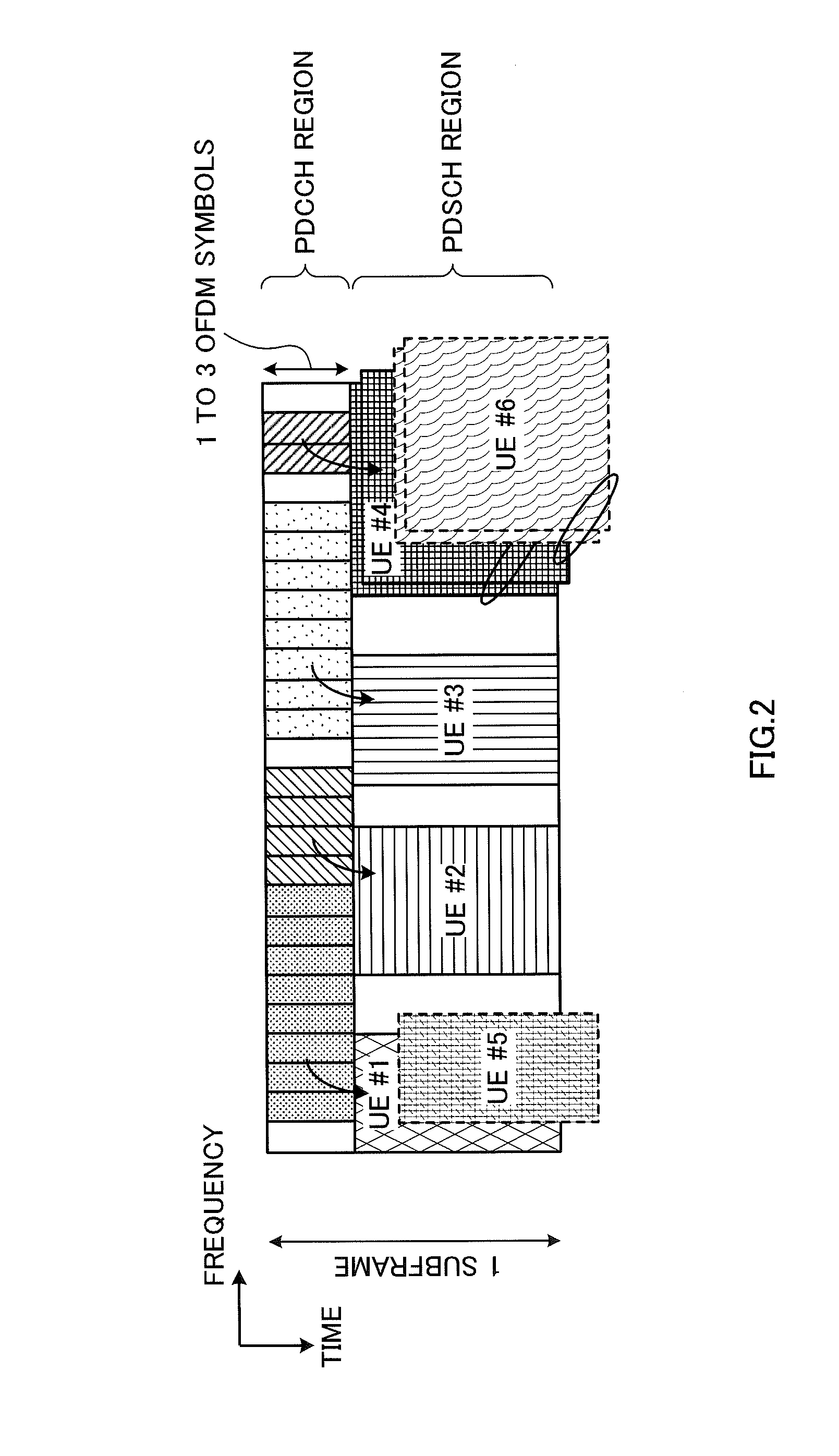
When a new transmission scheme such as the above one is employed, there is a threat that the capacity of the downlink control channel (PDCCH: Physical Downlink Control CHannel) to transmit downlink control information (DCI) runs short and the characteristics of the LTE-A system cannot be optimized.

Method used


Image

  • Radio communication system, user terminal and radio communication method
  • Radio communication system, user terminal and radio communication method
  • Radio communication system, user terminal and radio communication method

Examples


first example

[0041]As a first example, an example of carrying out RLM based on thresholds (second criteria) to support a new radio resource structure will be described. FIG. 5 is a schematic diagram to explain the RLM according to the first example. Hereinafter, the thresholds Qout and Qin (see FIG. 4) that are used in RLM optimized for conventional radio resource structures FIG. 5, the received quality measured with DM-RSs and the received quality measured with CRSs (see FIG. 4) are shown together.

[0042]As shown in FIG. 5, with the present example, when an enhanced PDCCH is configured, RLM is carried out based on thresholds Qout EPDCCH and Qin EPDCCH (second criteria), which are different from the conventional thresholds Qout PDCCH and Qin PDCCH. The threshold Qout EPDCCH corresponds to the threshold of the lower-level end, and is defined as received quality that is equivalent to a block error rate (BLER) of the enhanced PDCCH at which the downlink cannot be reliably received. Qin EPDCCH corres...

second example

[0051]As a second example, an example of carrying out RLM based on conventional thresholds (first criteria) will be described. With the present example, RLM is carried out based on conventional thresholds Qout PDCCH and Qin PDCCH (first criteria) even when an enhanced PDCCH is configured. That is to say, with the present example, the received quality of CRSs transmitted from the radio base station eNB is compared against the thresholds Qout PDCCH and Qin PDCCH, which correspond to BLERs of the PDCCH.

[0052]With the present embodiment, when the received quality measured with CRSs falls below the threshold Qout PDCCH, “out-of-sync,” which indicates a decrease of received quality, is detected. When this “out-of-sync” is detected a predetermined number of times in a row, the timer for judging RLFs is started. The number of times “out-of-sync” continues and triggers the timer is reported from the radio base station eNB to the user terminal UE through higher layer signaling.

[0053]When the ...

third example

[0055]An example of carrying out RLM by selectively using conventional thresholds (first criteria) and thresholds that support a new radio resource structure (second criteria) will be described with the present example. With the present example, one of the first example and the second example is used, selectively, depending on the states of the radio communication system.

[0056]For example, in the situation in which the communication performance of the enhanced PDCCH is better than the communication performance of the PDCCH, the first example is selected. In this case, the radio base station eNB reports to the user terminal UE that RLM is going to be carried out using the first criteria. The reporting may be sent using, for example, higher layer signaling. The user terminal UE carries out RLM by comparing the received quality of downlink reference signals from the radio base station eNB against thresholds Qout EPDCCH and Qin EPDCCH. The details are the same as in the first example.

[0...


PUM


Abstract

The present invention is designed to provide a radio communication system, a user terminal and a radio communication method that make it possible to monitor communication quality adequately even when a new radio resource structure is employed. A radio communication system is provided, which transmits downlink control information from a radio base station to a user terminal by using an enhanced downlink control channel that is frequency-division-multiplexed with a downlink shared data channel, and which also monitors downlink quality based on the received quality of downlink reference signals that are transmitted from the radio base station to the user terminal, and, in this radio communication system, the user terminal determines radio link failures by comparing the received quality of the downlink reference signals transmitted from the radio base station, against one or both of first criteria, which are constituted of two thresholds that correspond to predetermined block error rates of a downlink control channel, and second criteria, which are constituted of two thresholds that are different from the two thresholds of the first criteria.

Description

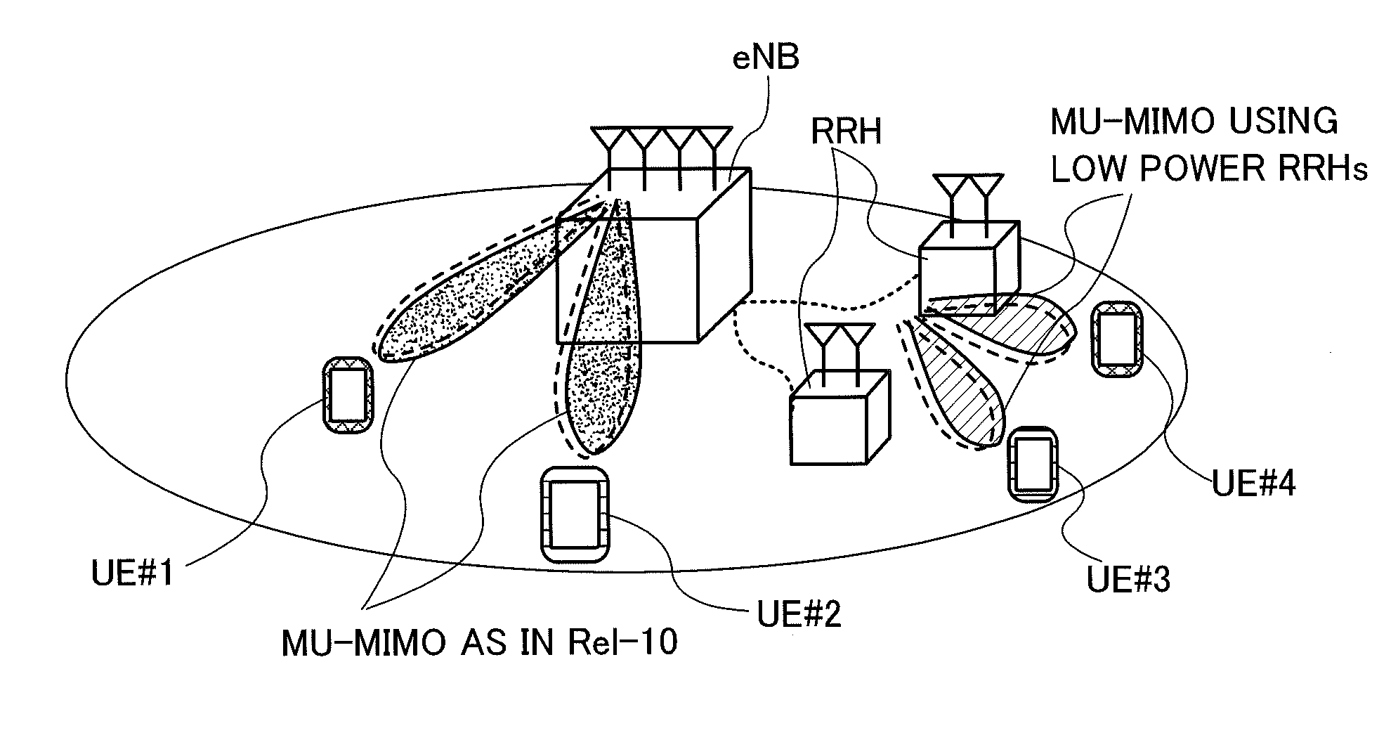
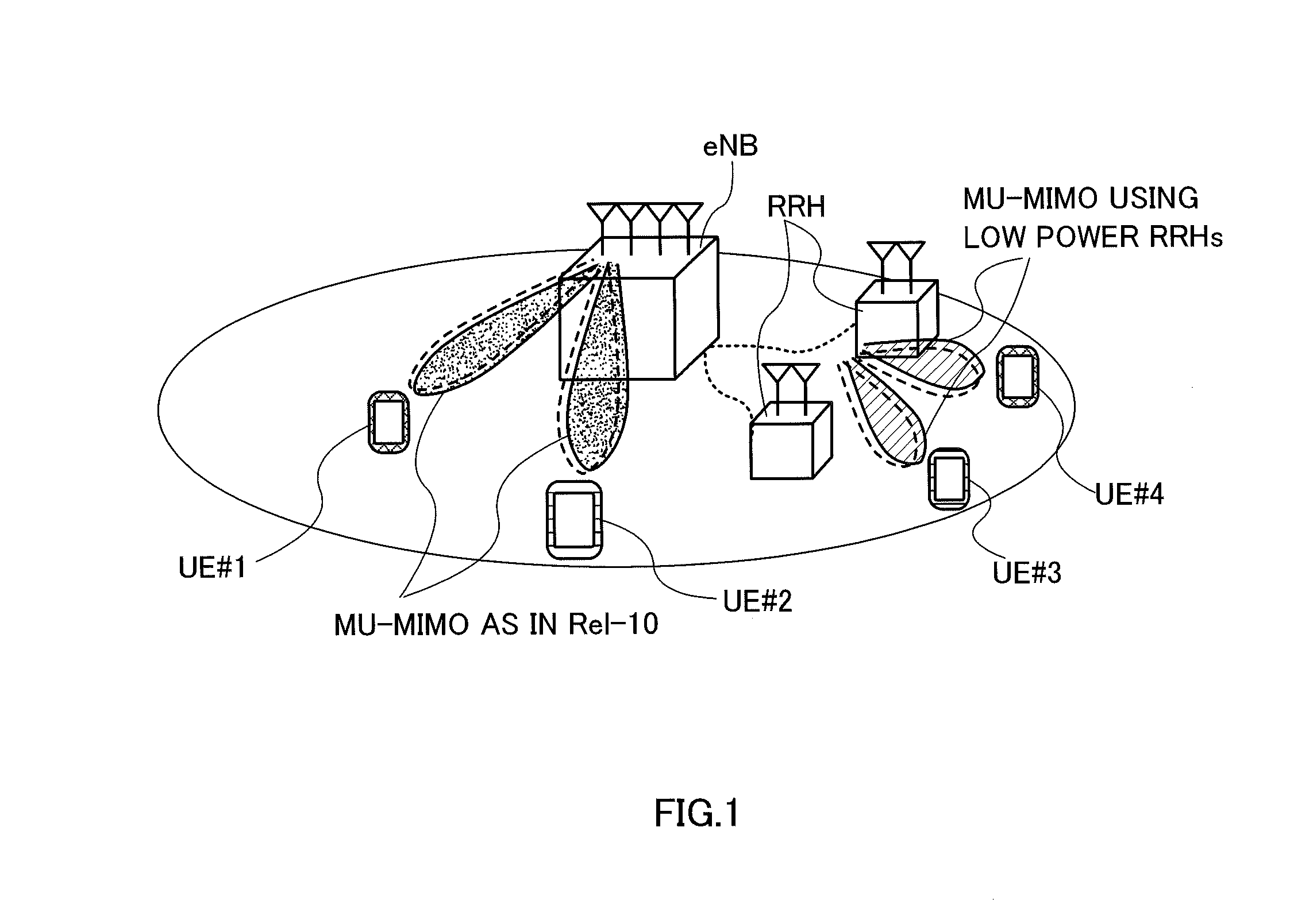
TECHNICAL FIELD[0001]The present invention relates to a radio communication system, a user terminal and a radio communication method.BACKGROUND ART[0002]The specifications of long-term evolution (LTE) have been developed for the purpose of achieving increased speed, lower delay and so on in UMTS (Universal Mobile Telecommunications System) (non-patent literature 1). In LTE, a communication scheme that is based on OFDMA (Orthogonal Frequency Division Multiple Access) is used in downlink channels (downlink), and a communication scheme that is based on SC-FDMA (Single Carrier Frequency Division Multiple Access) is used in uplink channels (uplink).[0003]Successor standards of LTE (referred to as “LTE-advanced” (“LTE-A”) and so on) are under study for the purpose of achieving further broadbandization and increased speed. LTE-A is planned to employ a new transmission scheme such as multiple-user MIMO (MU-MIMO), which transmits information from different transmitting antennas to different ...

Claims


Application Information

Patent Timeline
IPC IPC(8): H04W72/04H04W36/00H04L5/00H04W24/08H04W72/08
CPCH04W72/042H04W24/08H04W72/08H04W88/08H04W36/0055H04W88/02H04L5/0048H04W36/0058H04W36/0079H04W72/23H04W72/54
Inventor TAKEDA, KAZUAKIUCHINO, TOORUSAGAE, YUTATAKAHASHI, HIDEAKI
Owner NTT DOCOMO INC
Learn More