Eureka AIR delivers breakthrough ideas for toughest innovation challenges, trusted by R&D personnel around the world.

Cable Structure With Improved Clamping Configuration

a cable structure and configuration technology, applied in the field of cable structures, can solve the problems of difficult to obtain a good cable retention on a non-round cable assembly without damage to the cable, and difficulty in clamping the trunk wire, and achieve the effect of good cable retention

Inactive Publication Date: 2015-10-15
MOLEX INC
View PDF15 Cites 1 Cited by
  • Summary
  • Abstract
  • Description
  • Claims
  • Application Information

AI Technical Summary

Benefits of technology

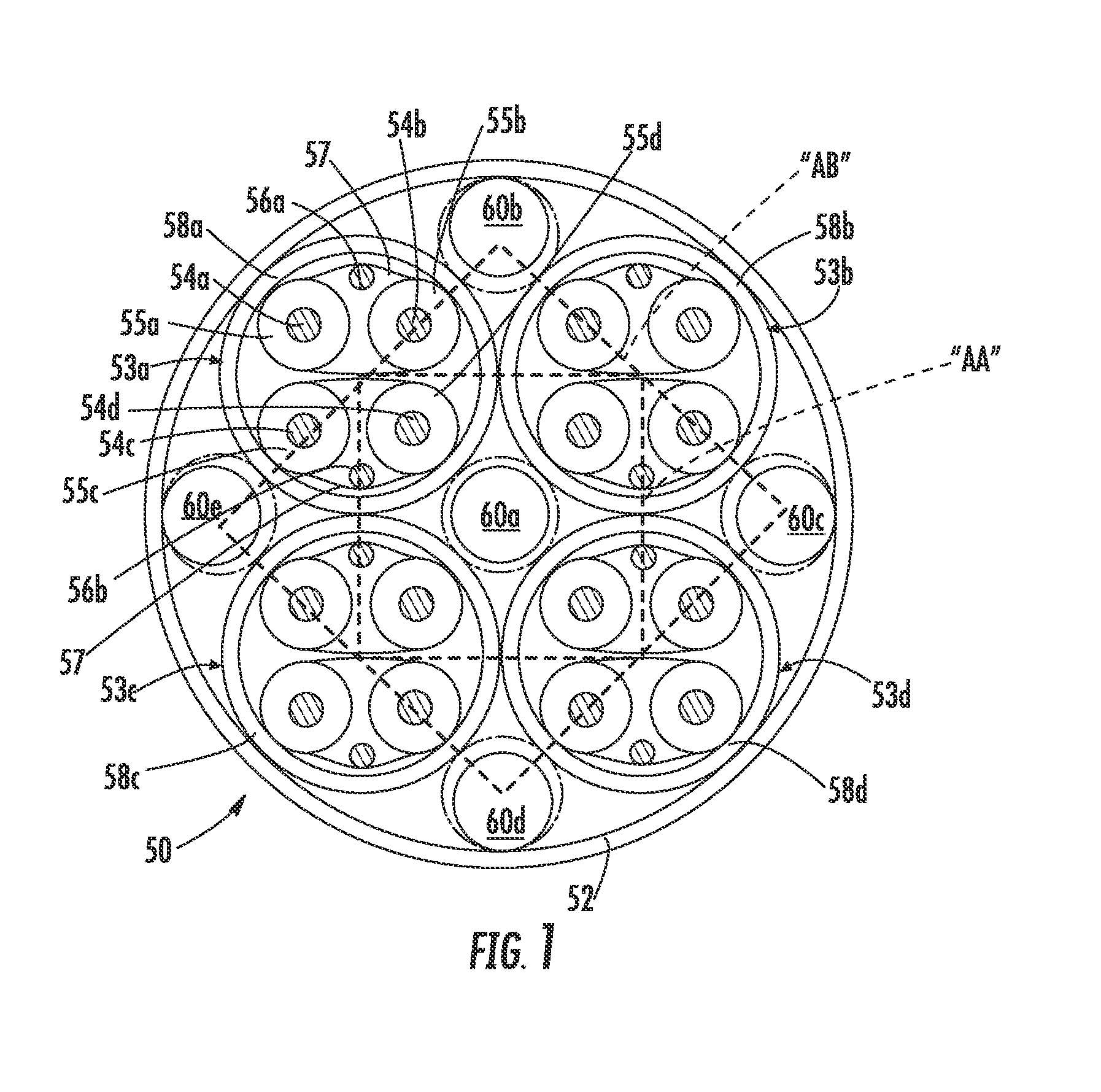
This patent describes a method for making a circular QSFP cable by adding insulative material between the cables and in the middle of the cable to ensure a proper placement and prevent the formation of a catenary. This results in a more rounded continuous circular profile between the cables, which is important for securing the cable to a backshell without damaging it. The technical effect is a more robust and secure attachment of the cable to the backshell.

Problems solved by technology

Either of these configurations present difficulties in clamping the trunk wire in a backshell by way of undesirable EMI openings or pinching of the trunk cable insulation.
Accordingly, it would be difficult to obtain a good cable retention on a non-round cable assembly without doing damage to the cable.

Method used


Image

  • Cable Structure With Improved Clamping Configuration
  • Cable Structure With Improved Clamping Configuration
  • Cable Structure With Improved Clamping Configuration

Examples


Embodiment Construction

[0017]While the Present Disclosure may be susceptible to embodiment in different forms, there is shown in the Figures, and will be described herein in detail, specific embodiments, with the understanding that the Present Disclosure is to be considered an exemplification of the principles of the Present Disclosure, and is not intended to limit the Present Disclosure to that as illustrated.

[0018]As such, references to a feature or aspect are intended to describe a feature or aspect of an example of the Present Disclosure, not to imply that every embodiment thereof must have the described feature or aspect. Furthermore, it should be noted that the description illustrates a number of features. While certain features have been combined together to illustrate potential system designs, those features may also be used in other combinations not expressly disclosed. Thus, the depicted combinations are not intended to be limiting, unless otherwise noted.

[0019]In the embodiments illustrated in ...


PUM


Abstract

A cable used in high speed applications contains four internal cables with two wire pairs in each cable. The internal cables are protected by only a conductive braided shield and are arranged in the cable adjacent each other. At least four non-conductive blanks are disposed in the gaps which occur between adjacent ones of the internal cables. The blanks serve to prevent the cable outer insulation from sagging into the gaps between the internal cables so that the cable has a substantially circular configuration.

Description

BACKGROUND OF THE PRESENT DISCLOSURE[0001]The Present Disclosure relates generally to cable structures, and, more particularly, to a high speed cable structure with an improved clamping configuration.[0002]The use of high speed data transmission cables is ever growing. As the need for connectivity increases, high speed cables are needed to provide connections between various devices, such as routers and switches, etc. A number of standards have been developed for data communication. One such standard is the Quad Small Form-factor Pluggable (QSFP) standard, which pertains to compact, hot-pluggable transceivers. It serves to provide an interface between high speed devices such as routers, motherboards, switches, media converters and the like and fiber optic data cables and devices.[0003]QSFP cables typically include four SFP cables enclosed in a trunk cable. Such cables are typically manufactured by twist or binding four SFP cables together. The assembly of these four SFP cables into ...

Claims


Application Information

Patent Timeline
IPC IPC(8): G02B6/38
CPCG02B6/3887H01B11/20H01B7/1895
Inventor BYCZKIEWICZ, BARBARALLOYD, BRIAN KEITH
Owner MOLEX INC
Why Eureka
Eureka Blog
Learn More