Fiber-reinforced turbine component

Inactive Publication Date: 2015-10-15
IHI CORP
View PDF2 Cites 8 Cited by
  • Summary
  • Abstract
  • Description
  • Claims
  • Application Information

AI Technical Summary

Benefits of technology

The turbine component described in this patent is designed to have enough strength even in a specific section called a dovetail.

Problems solved by technology

Interlayers among the reinforcement fiber fabrics, however, lack connection by the reinforcement fibers.
As high-strength of CMC depends largely on the reinforcement fibers, such sites are significantly inferior in strength and are therefore susceptible to exfoliation or shear failure.
It consequently raises some concerns that shear failure would occur.

Method used


Image

  • Fiber-reinforced turbine component
  • Fiber-reinforced turbine component
  • Fiber-reinforced turbine component

Examples


Embodiment Construction

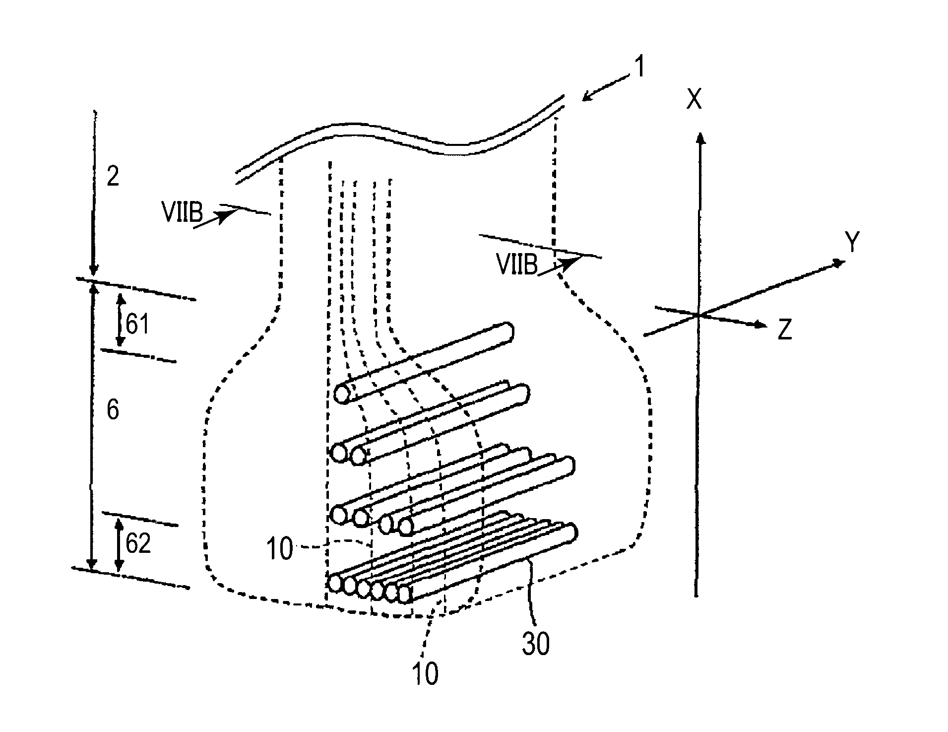
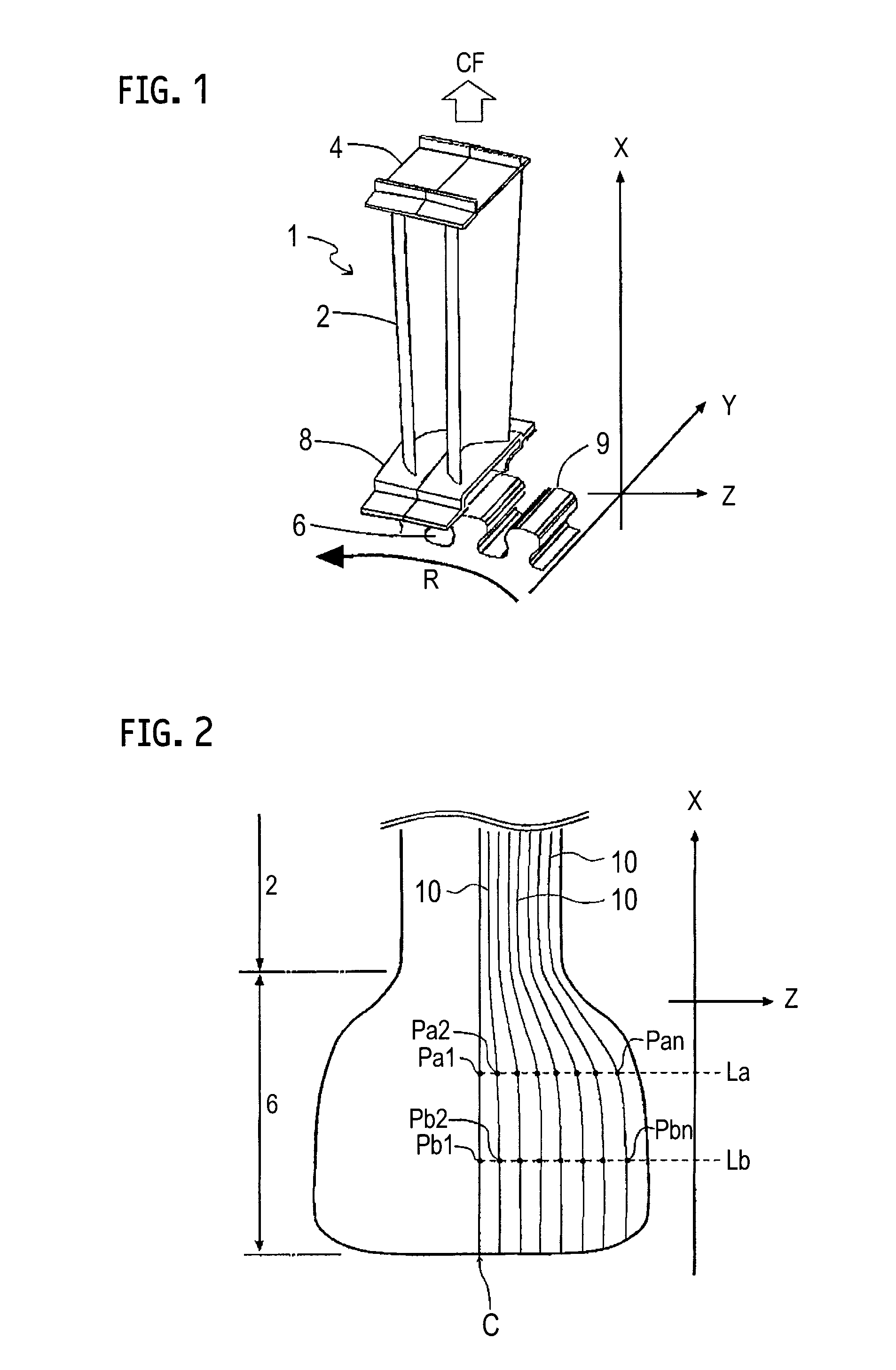
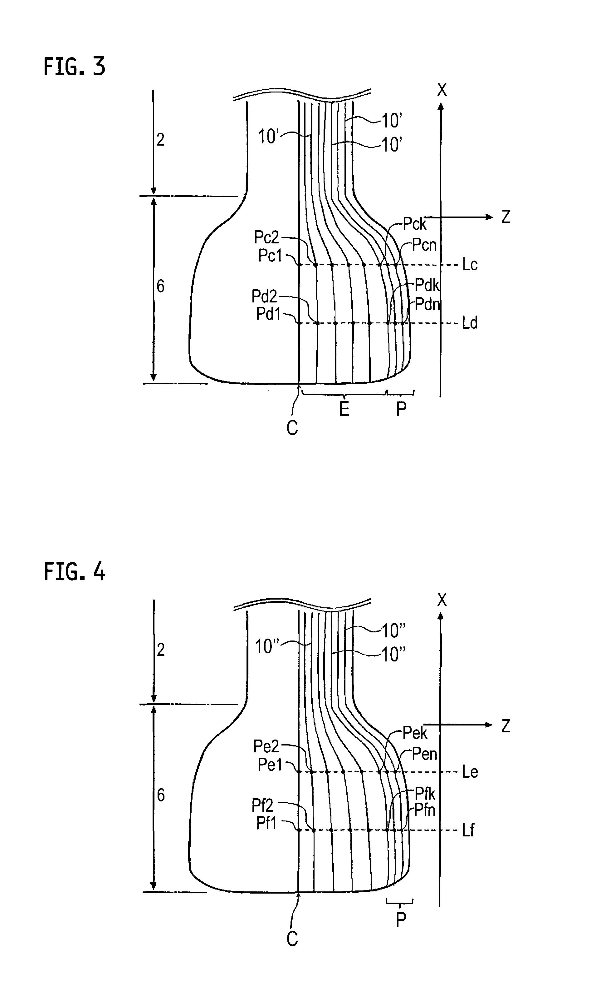
[0023]Exemplary embodiments will be described hereinafter with reference to the appended drawings.

[0024]The present embodiment is applicable to a turbine component of a complex shape, such as a turbine rotor blade, but is applicable also to many various machine components that require high-temperature strength. The present embodiment will be described hereinafter with reference to an example of a turbine rotor blade 1 exemplified in FIG. 1.

[0025]Throughout the present specification and the appended claims, as a radial direction of a turbine is consistent with a longitudinal direction of the turbine rotor blade, this will be referred to as a longitudinal direction. Similarly, an axial direction of the turbine will be referred to as a depth direction and a tangential direction of rotation of the turbine will be referred to as a width direction. In the drawings and the following descriptions, signs X, Y and Z respectively indicate the longitudinal direction, the depth direction and the...


PUM

PropertyMeasurementUnit
Widthaaaaaaaaaa

Abstract

A turbine component includes an airfoil section elongated in a longitudinal direction; a dovetail section continuous with an end of the airfoil section and bulging in a width direction across the longitudinal direction; a plurality of first reinforcement fibers running continuously from the airfoil section to the dovetail section; a plurality of second reinforcement fibers running at least partly in the width direction in the airfoil section; and a matrix joining an entirety of the first reinforcement fibers and the second reinforcement fibers. In the airfoil section, the second reinforcement fibers are woven into the first reinforcement fibers to form a three-dimensional fabric. In the dovetail section, the first reinforcement fibers are not gathered in the width direction by other fibers but deploy in the width direction.

Description

CROSS-REFERENCE TO RELATED APPLICATIONS[0001]This application is a Continuation Application of PCT International Application No. PCT / JP2013 / 084882 (filed Dec. 26, 2013), the entire contents of which are incorporated herein by reference.BACKGROUND[0002]1. Field of the Disclosure[0003]The present disclosure relates to a fiber-reinforced turbine component and, in particular, relates to a turbine rotor blade of a ceramic matrix composite including reinforcement fibers.[0004]2. Description of the Related Art[0005]An aeronautic turbofan engine is, as exemplified in FIG. 8A, comprised of plural stages of turbines so as to extract energy from combustion gas, and each stage of the turbine is comprised of plural turbine blades arranged around a turbine disk. Each turbine blade 100 is, as exemplified in FIG. 8B, comprised of an airfoil section 102, a tip shroud section 104 surrounding it at its outside, a platform section 108 surrounding it at its inside, and a dovetail section 106 for couplin...

Claims


Application Information

Patent Timeline
IPC IPC(8): F01D5/28F01D5/30F01D5/14
CPCF01D5/282F01D5/147F01D5/284F05D2240/30F05D2300/6033F05D2220/30F01D5/3007C04B35/80F05D2300/2282F05D2300/2283F05D2300/2261F05D2300/2112D03D25/005D10B2505/02C04B2235/524C04B2235/5244C04B2235/5248C04B2235/5252C04B2235/5268D03D1/00D10B2101/08F05D2300/6034Y02T50/60C04B35/565C04B35/584C04B35/117C04B35/581C04B35/83
Inventor KAWANISHI, KENNAKAMURA, TAKESHIWATANABE, FUMIAKI
Owner IHI CORP
Why Eureka
Try Eureka