
Aeration device, operation method therefor, and water treatment apparatus

a technology of aeration device and water treatment apparatus, which is applied in the direction of carburetor air, biological water/sewage treatment, and membranes, etc., can solve the problems of degrading the function of the membrane module, the membrane module is not sufficiently washed, and the aeration device is not uniformly performed, etc., and achieves convenient installation

Inactive Publication Date: 2015-10-15
MITSUBISHI CHEM CORP
View PDF3 Cites 5 Cited by
  • Summary
  • Abstract
  • Description
  • Claims
  • Application Information

AI Technical Summary

Benefits of technology

The invention is about an aeration device that can effectively and uniformly aerate water. It is easy to install, has simple piping, and an operation method that is straightforward. The device can be used in water treatment apparatuses.

Problems solved by technology

However, in this case, a turbulent flow of the gas for aeration is easily generated near the distal end(s) 11b in the aeration pipe 11, and aeration from the aeration holes 14 on a side of the distal end(s) 11b is not uniformly performed.
As a result, there is a problem in that the membrane module is not sufficiently washed due to non-uniform aeration, and a function of the membrane module is degraded due to attached sludge and the like (clocking).
However, there is a problem in that running cost, equipment cost, and the like due to increase in electricity consumption soar as an air flow of aeration increases.

Method used


Image

  • Aeration device, operation method therefor, and water treatment apparatus
  • Aeration device, operation method therefor, and water treatment apparatus
  • Aeration device, operation method therefor, and water treatment apparatus

Examples


example 1

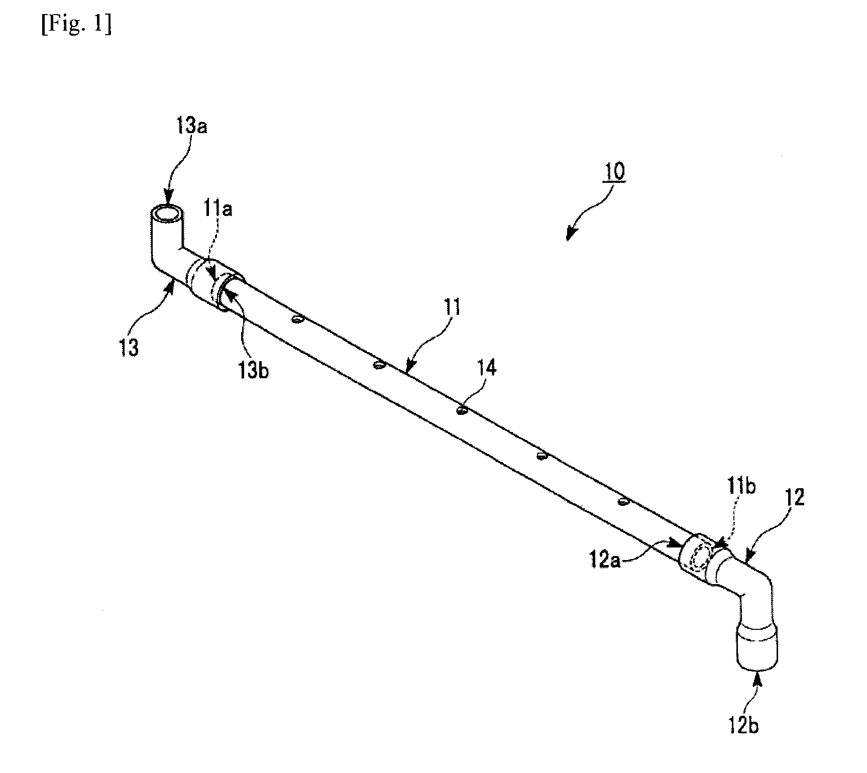
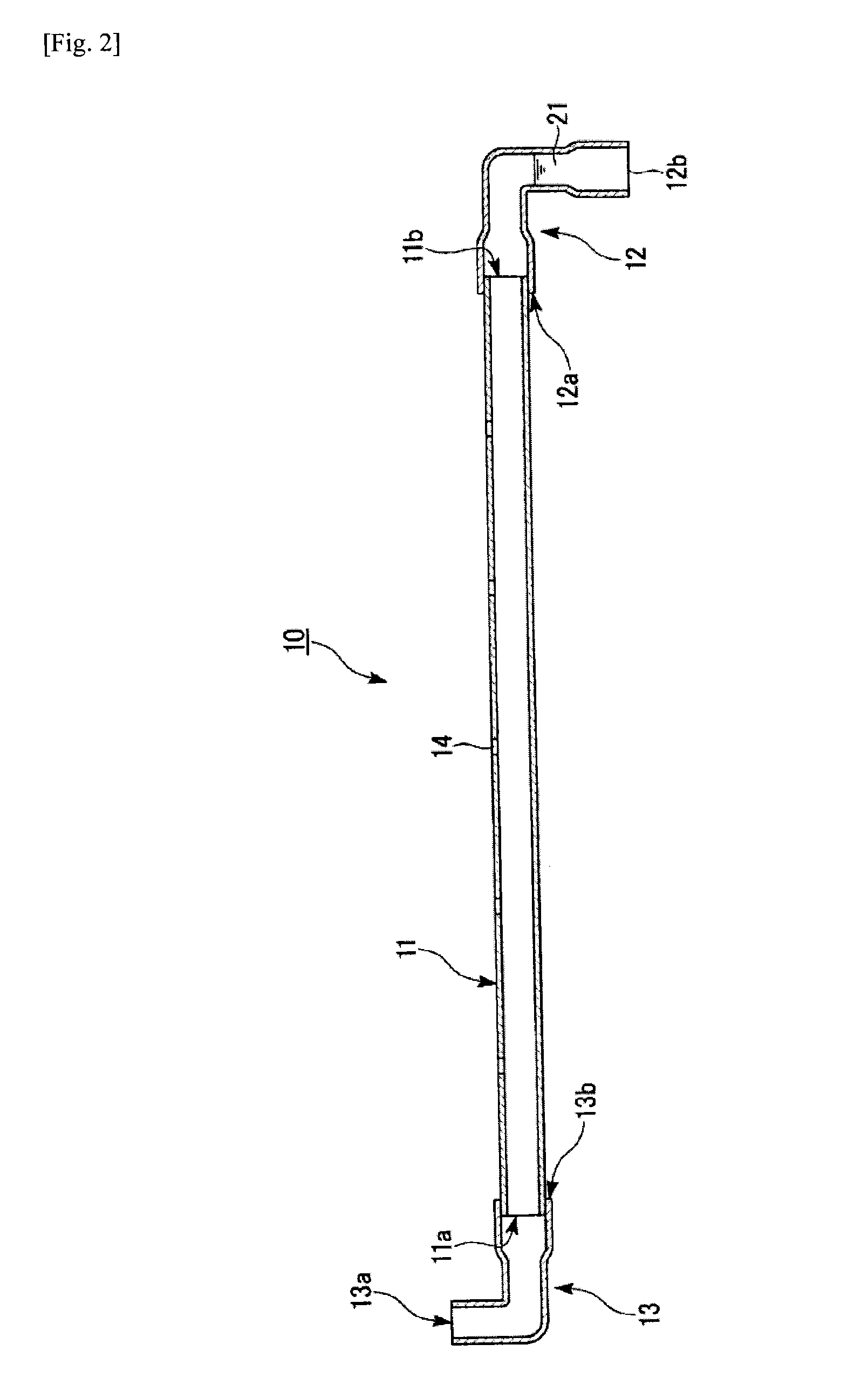
[0169]One aeration pipe extending in a horizontal direction in which an internal diameter D was 20.0 mm, a length L was 500 mm, and five equally spaced circular aeration holes, each of which had a diameter d of 6.0 mm, were formed in an upper portion thereof was used as the aeration pipe.

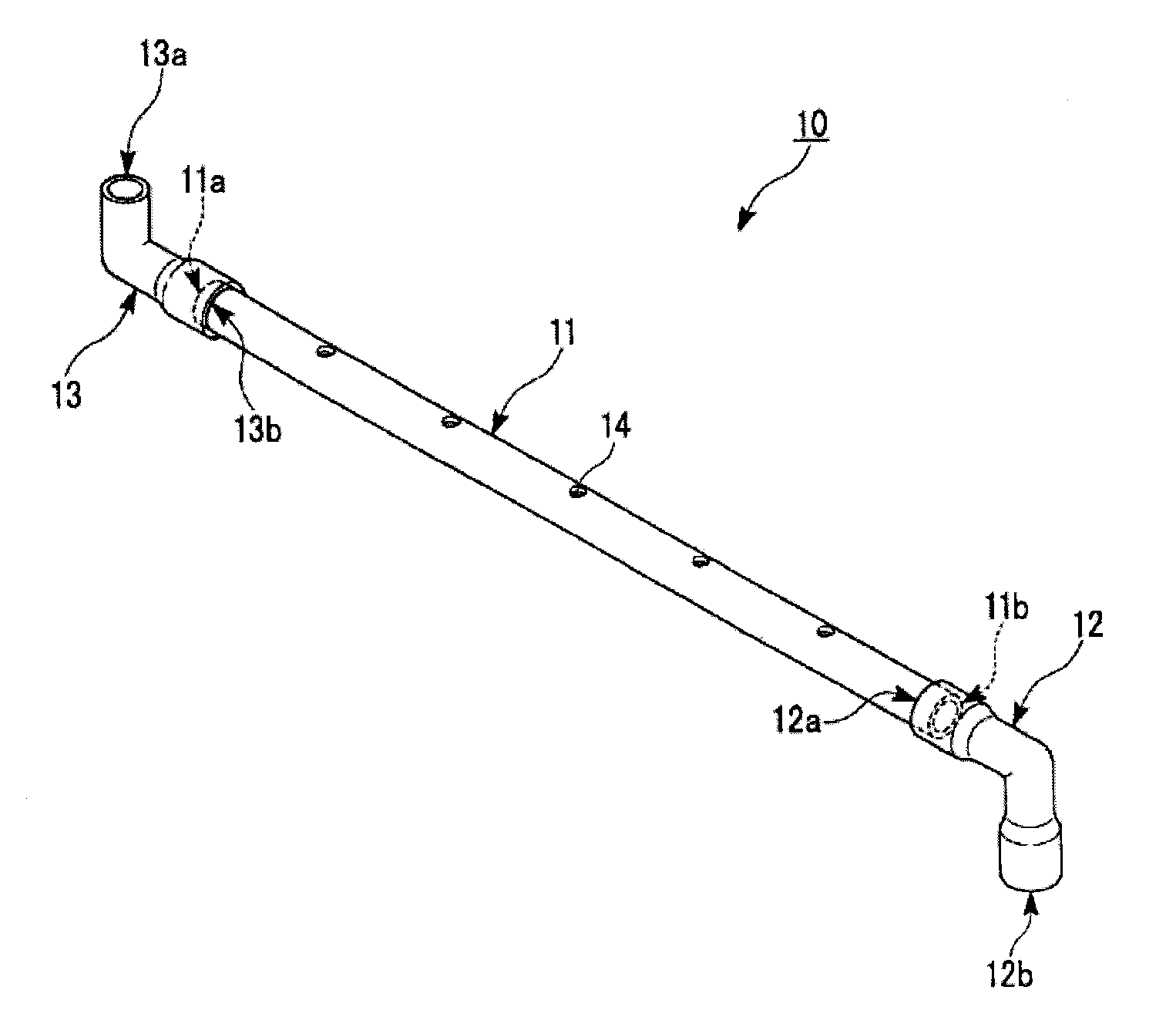
[0170]The other end of a connecting member was allowed to communicate with a base end of the aeration pipe. In addition, one end of an opening pipe, in which the other end was open downward in a vertical direction and the other end side extended downward in the vertical direction and was allowed to directly communicate with a distal end of the aeration pipe, was formed as the aeration device 10 illustrated in FIG. 1. A 90° elbow pipe was used as the opening pipe.

[0171]A gas supply pipe of a gas supply device was connected to one end of the connecting member, and air was supplied from the gas supply device to the aeration pipe of the aeration device at an air flow of 100 l / min.

[0172]A flow rate of ai...

example 2

[0177]A characteristic of aeration was evaluated similarly to Example 1 except that the internal diameter D of the aeration pipe was changed to 13.0 mm. Results are shown in Tables 1 and 2.

[0178]A flow rate of air flowing in the aeration pipe was 12.6 m / s. In addition, an air flow of air diffused from each aeration hole was 20.0 l / min per aeration hole. Further, flow rates of air diffused from the respective aeration holes were 10.6 m / s, 10.7 m / s, 11.6 m / s, 12.4 m / s, and 13.7 m / s in order from the side of the base end of the aeration pipe, and an average flow rate thereof was 11.8 m / s. The flow rates of air diffused from the respective aeration holes were obtained by setting the cross-sectional area of each of the aeration holes to 2.83×10⁻⁵ m2.

example 3

[0179]A characteristic of aeration was evaluated similarly to Example 1 except that the internal diameter D of the aeration pipe was changed to 13.0 mm, and the air flow of air supplied to the aeration pipe of the aeration device from the gas supply device was changed to 75 l / min. Results are shown in Tables 1 and 2.

[0180]A flow rate of air flowing in the aeration pipe was 9.4 m / s. In addition, an air flow of air diffused from each aeration hole was 15.0 l / min per aeration hole. Further, flow rates of air diffused from the respective aeration holes were 8.4 m / s, 8.2 m / s, 8.6 m / s, 9.3 m / s, and 9.8 m / s in order from the side of the base end of the aeration pipe, and an average flow rate thereof was 8.9 m / s. The flow rates of air diffused from the respective aeration holes were obtained by setting the cross-sectional area of each of the aeration holes to 2.83×10⁻⁵ m2.


PUM

PropertyMeasurementUnit
lengthaaaaaaaaaa
diameteraaaaaaaaaa
internal diameteraaaaaaaaaa

Abstract

The present invention relates to an aeration device provided with: an aeration tube, in the upper part of which multiple aeration holes are formed and which extends in the horizontal direction; and an open-ended tube. One end of the open-ended tube directly or indirectly communicates with an end of the aeration tube and the open end of the open-ended tube opens downward in the vertical direction and satisfies formula (1). The present invention provides: an aeration device, which is capable of uniform aeration, can be placed conveniently, and with which complication of tube placement does not occur easily; an operation method therefor; and a water treatment apparatus provided with the aeration device.(D×d×n) / Q≦7.5  (1)(In formula (1), (D) is the internal diameter (mm) of the aeration tube, (d) is the diameter (mm) of the aeration holes, (n) is the number of aeration holes per one aeration tube, and (Q) is the air flow (l / min) of the gas supplied per one aeration tube.)

Description

TECHNICAL FIELD[0001]The present invention relates to an aeration device disposed below a membrane module unit, an operation method for the same, and a water treatment apparatus including the aeration device disposed below the membrane module unit.[0002]The invention claims the benefits of Japanese Patent Applications No. 2012-235750, filed on Oct. 25, 2012 and No. 2012-256145, filed on Nov. 22, 2012, in the Japanese Intellectual Property Office, the entire disclosures of which are incorporated herein.BACKGROUND ART[0003]In a conventional scheme, an aeration device including an aeration pipe in which a plurality of aeration holes are formed is disposed in a water tank of a water treatment apparatus including a membrane module unit (for example, activated sludge treatment equipment, membrane washing equipment, membrane separation device, waste water treatment equipment, and the like) such that the aeration device is positioned below the membrane module unit, gas for aeration such as ...

Claims


Application Information

Patent Timeline
Patent Type & Authority Applications(United States)
IPC IPC(8): B01D65/02C02F1/44B01D61/00B01F3/04
CPCB01D65/02B01F3/04262C02F2303/20B01D61/00B01D2321/185C02F1/44C02F1/444C02F3/1273C02F3/201B01D61/20B01D2313/26B01F2215/0409B01F2215/0431B01F2215/045C02F3/208Y02W10/10B01F23/23113B01F23/23115B01F23/23125B01F23/23121B01F23/231265B01F23/23123
Inventor ZOU, ZHUOYISASAKAWA, MANABUFURUNO, SHINSUKE
Owner MITSUBISHI CHEM CORP
Learn More