Vehicular lamp

a technology of vehicle lamp and lamp chamber, which is applied in the field of lamps, can solve the problems of increasing component cost and assembly time, adversely affecting appearance, and difficult to see the substrate supporting the light-emitting element from the outside of the lamp chamber

Active Publication Date: 2015-10-08
KOITO MFG CO LTD
View PDF5 Cites 4 Cited by
  • Summary
  • Abstract
  • Description
  • Claims
  • Application Information

AI Technical Summary

Benefits of technology

[0006]Light emitted from light-emitting elements are radiated in a predetermined direction through a translucent cover that defines a lamp chamber. Since the light-emitting elements are mounted on a flexible circuit board, the flexible circuit board can be seen through the translucent cover when the light-emitting elements are unlit, which adversely affects the appearance. In view of the above, a cover that covers up the flexible circuit board is required. This may increase component cost and assembly time.
[0007]One or more embodiments of the present invention may avoid an increase in component cost and assembly time without adversely affecting the appearance even when light-emitting elements are unlit.

Problems solved by technology

Since the light-emitting elements are mounted on a flexible circuit board, the flexible circuit board can be seen through the translucent cover when the light-emitting elements are unlit, which adversely affects the appearance.
This may increase component cost and assembly time.
Accordingly, even when the light-emitting element is unlit, it is difficult to see the substrate supporting the light-emitting element from the outside of a lamp chamber.

Method used


Image

  • Vehicular lamp
  • Vehicular lamp
  • Vehicular lamp

Examples


Embodiment Construction

[0020]Embodiments of the present invention will be described in detail below with reference to the accompanying drawings. In each figure used in the following description, the scale of each member has been changed as appropriate in order to allow each member to have a recognizable size. The terms “right” and “left” as used in the following description refer to the right and left as viewed from the driver's seat. In embodiments of the invention, numerous specific details are set forth in order to provide a more thorough understanding of the invention. However, it will be apparent to one of ordinary skill in the art that the invention may be practiced without these specific details. In other instances, well-known features have not been described in detail to avoid obscuring the invention.

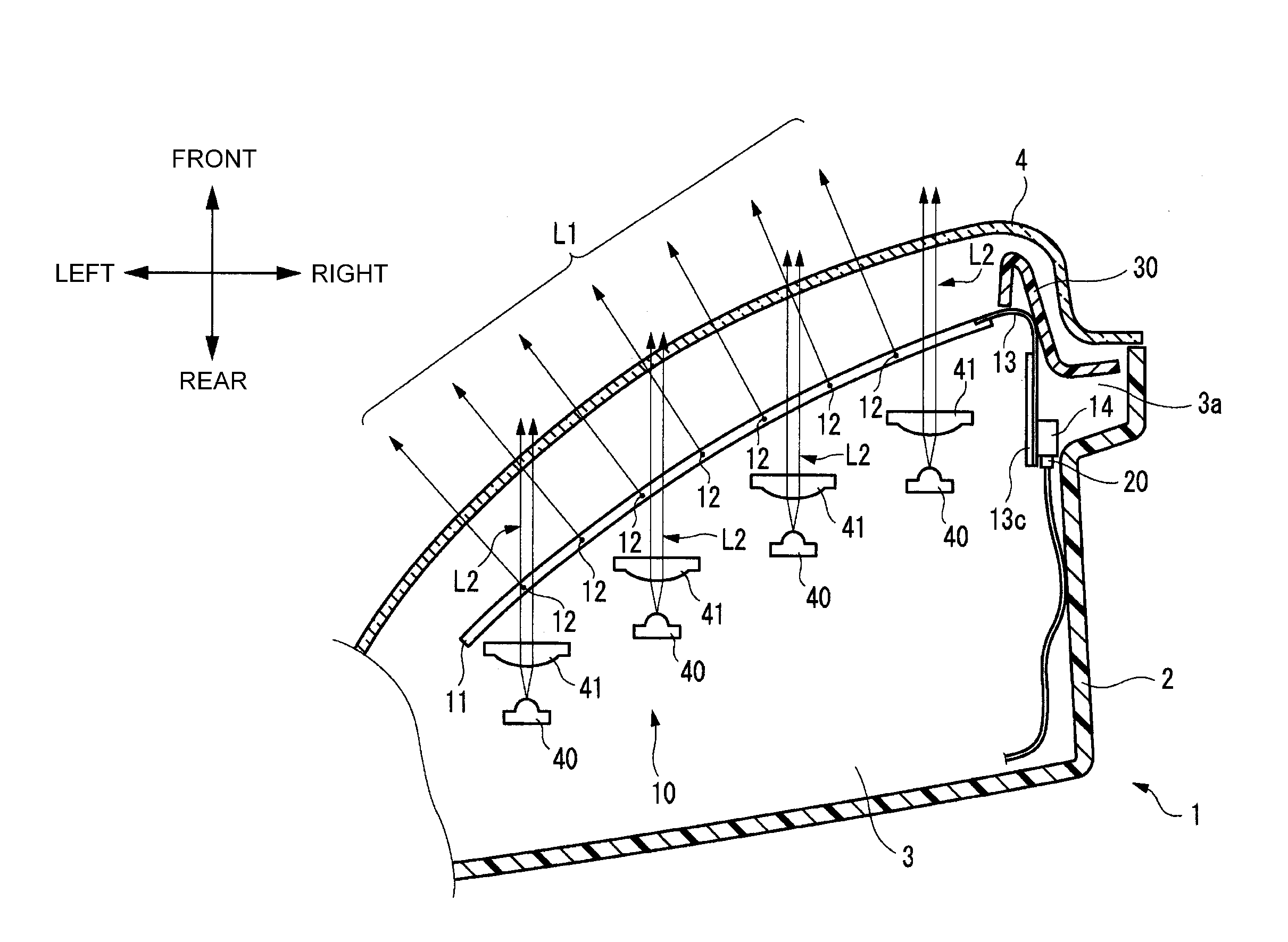
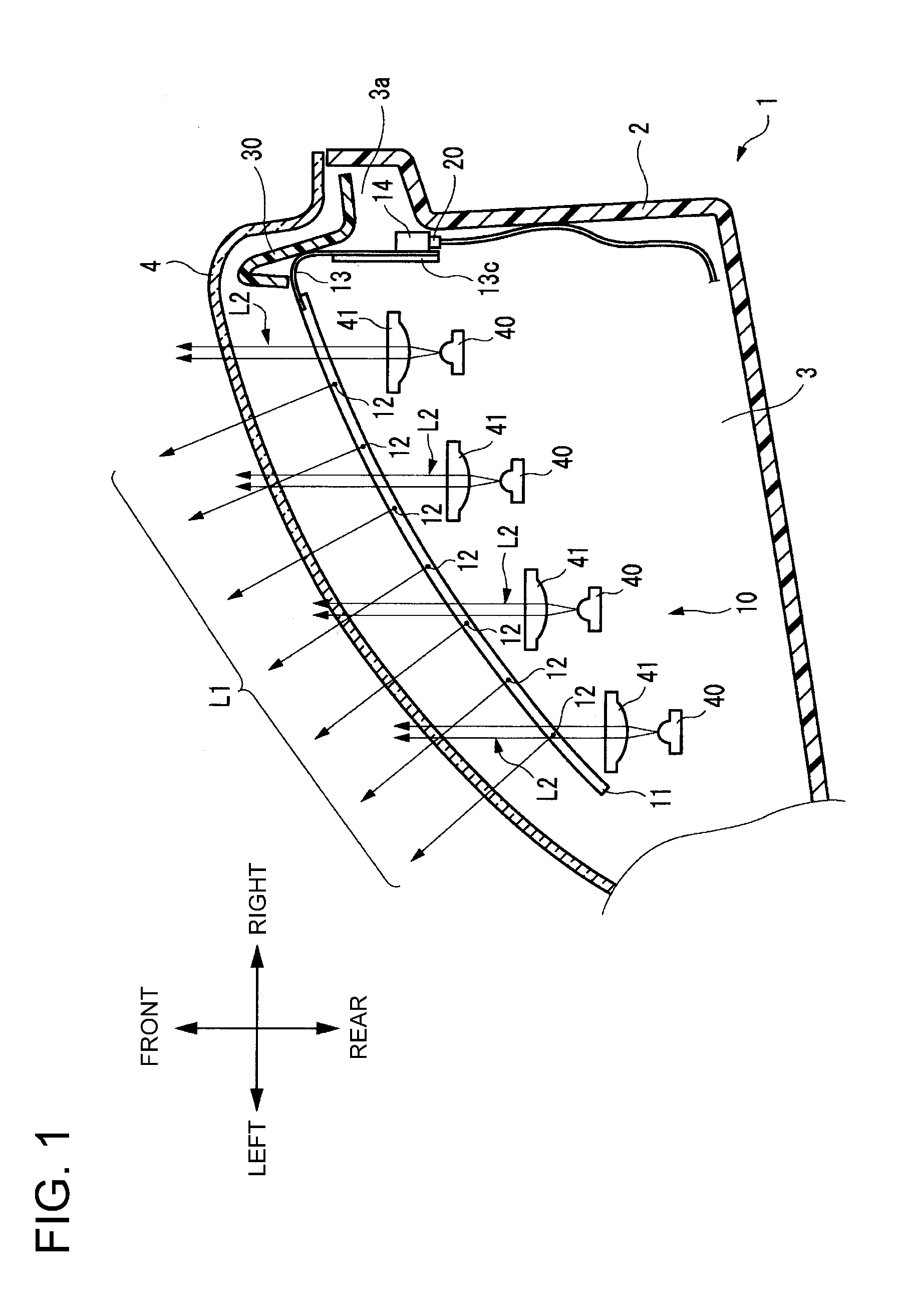
[0021]FIG. 1 is a diagram showing a part of a left headlamp device 1 according to one or more embodiments of the present invention, taken along a horizontal plane and viewed from above. The left headl...


PUM


Abstract

A lamp that is mounted on a vehicle has a transparent substrate including a conductive layer, a light-emitting element supported by the transparent substrate and electrically connected to the conductive layer, a connection portion electrically connected to the conductive layer at an end of the transparent substrate, and a connector electrically connected to the connection portion.

Description

BACKGROUND[0001]1. Technical Field[0002]The present invention relates to lamps that are mounted on vehicles.[0003]2. Related Art[0004]Lamps in which a flexible circuit board having light-emitting elements as light sources mounted thereon is disposed in a lamp chamber are known as this type of lamp (see, e.g., Patent Document 1). Since flexible substrates are deformable due to their flexibility, the use of flexible substrates can increase the freedom of design choice with respect to arrangement of the light-emitting elements in the lamp chamber.RELATED ART DOCUMENTS[0005]Patent Document 1: Japanese Patent Application Laid-Open (Kokai) No. 2010-15910SUMMARY[0006]Light emitted from light-emitting elements are radiated in a predetermined direction through a translucent cover that defines a lamp chamber. Since the light-emitting elements are mounted on a flexible circuit board, the flexible circuit board can be seen through the translucent cover when the light-emitting elements are unlit...

Claims


Application Information

Patent Timeline
Patent Type & Authority Applications(United States)
IPC IPC(8): B60Q1/00B60Q1/04H05K1/18F21W107/10
CPCB60Q1/0088B60Q1/04H05K1/189F21V23/06F21S41/00F21S41/18F21S43/00F21S43/10B60Q1/0058F21Y2103/10F21Y2103/30F21Y2109/00F21S41/151F21S41/255F21S41/285F21S43/14F21S43/15F21S43/195H05K1/0281H05K2201/10106
Inventor NAKAMURA, HIROMI
Owner KOITO MFG CO LTD
Why Eureka
Try Eureka