Systems and methods for modeling fracture networks in reservoir volumes from microseismic events

a technology of reservoir volume and fracture network, applied in the field of system and method for modeling fracture network in reservoir volume from microseismic event, and modeling fracture or pipe network resulting, can solve the problem of typical heterogeneous rock

Active Publication Date: 2015-10-01
ASPEN PARADIGM HLDG LLC
View PDF5 Cites 21 Cited by
  • Summary
  • Abstract
  • Description
  • Claims
  • Application Information

AI Technical Summary

Benefits of technology

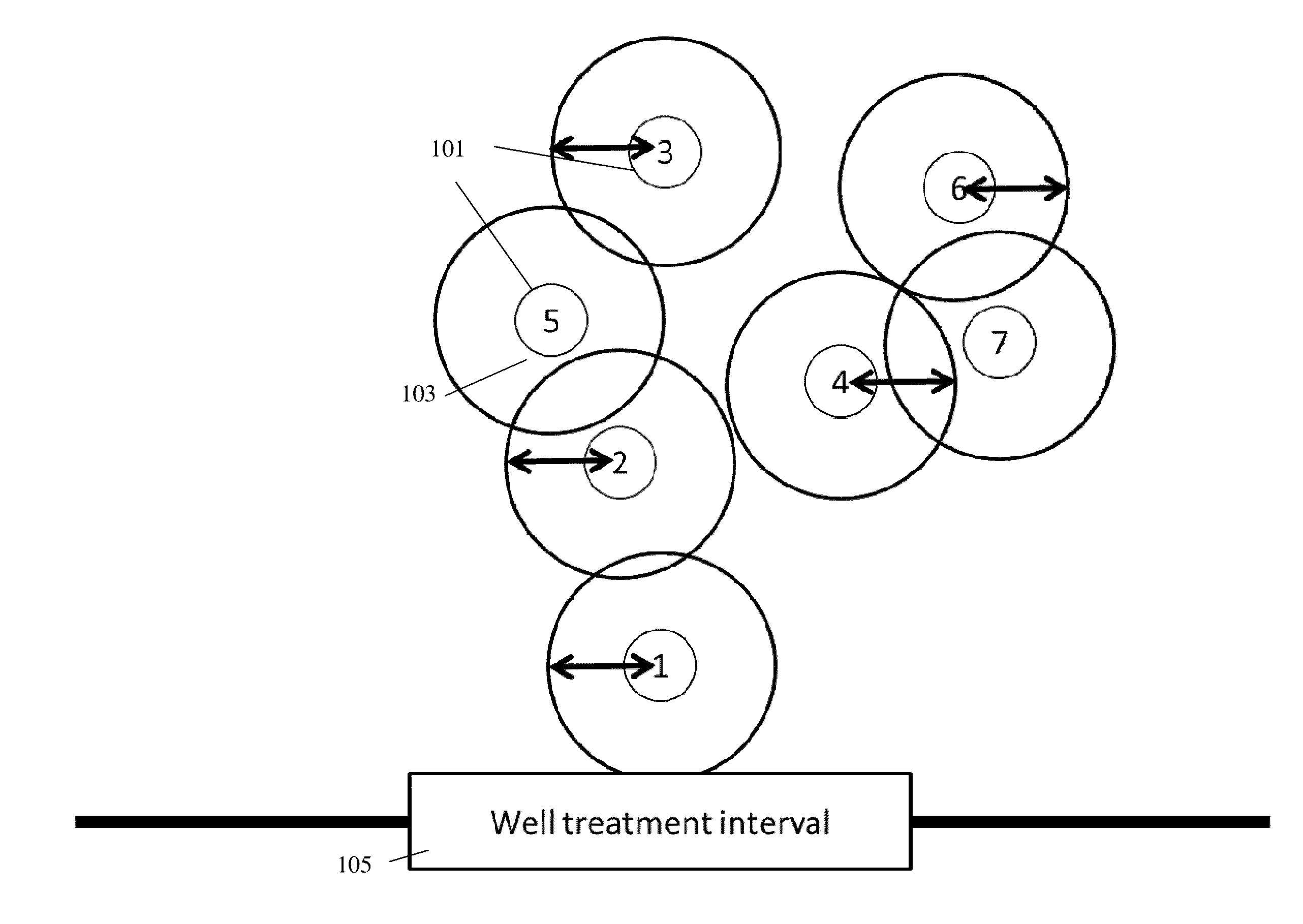
[0007]Embodiments of the invention may model or visualize a fracture network or pipe network based on microseismic events and/or perforated intervals of wells. The fracture network model may take into account the heterogeneous properties of fractured rock by modeling the flow of liquid along the paths of fracture lines. A time-dependent fracture network may be modelled based on the location and timing of microseismic events using a discrete fracture network approach which defines connections between microseismic events and a network that includes previous microseismic events. Each microseismic event, which is recorded at a specific time, may be added to the network in chronological order to iteratively expand the network until all recorded events are modeled. Each new event may be connected to the network by an “event-to-event” fracture, an “event-to-network” fracture, or an “anisotropic” fracture, discussed in more detail below.
[0008]According to an embodiment of the invention, data may be received associated with a set of microseismic events and a fracture network, where the data associated with each microseismic event includes a location where, and a time when, the microseismic event was recorded by one or more sensors e.g. geophones. Each microseismic event in the set may be sequentially added to

Problems solved by technology

However, in reality, rock is typically heterogeneous and liquid tends to flow a

Method used


Image

  • Systems and methods for modeling fracture networks in reservoir volumes from microseismic events
  • Systems and methods for modeling fracture networks in reservoir volumes from microseismic events
  • Systems and methods for modeling fracture networks in reservoir volumes from microseismic events

Examples


Embodiment Construction

[0022]In the following description, various aspects of the present invention will be described. For purposes of explanation, specific configurations and details are set forth in order to provide a thorough understanding of the present invention. However, it will also be apparent to one skilled in the art that the present invention may be practiced without the specific details presented herein. Furthermore, well known features may be omitted or simplified in order not to obscure the present invention.

[0023]Unless specifically stated otherwise, as apparent from the following discussions, it is appreciated that throughout the specification discussions utilizing terms such as “processing,”“computing,”“calculating,”“determining,” or the like, refer to the action and / or processes of a computer or computing system, or similar electronic computing device, that manipulates and / or transforms data represented as physical, such as electronic, quantities within the computing system's registers a...


PUM


Abstract

A system and method for receiving data associated with a set of microseismic events and a fracture network, the data associated with each microseismic event including a location where, and a time when, the microseismic event was recorded by one or more sensors. Each microseismic event in the set may be added to a fracture network in chronological order of the time when the microseismic event was recorded. Each microseismic event may be added by connecting the event to the fracture network by a fracture according to a connection criterion. A stimulated rock volume may be generated that is defined by an iso-surface of points having a constant distance to the fracture network, wherein the fracture network includes a plurality of microseismic events in the set and a plurality of fractures connecting the plurality of microseismic events according to the connection criterion.

Description

CROSS REFERENCE TO RELATED APPLICATIONS[0001]This application claims benefit of U.S. Provisional Patent Application No. 61 / 971,648 filed on Mar. 28, 2014, which is incorporated herein by reference in its entirety.FIELD OF THE PRESENT INVENTION[0002]Embodiments of the invention may relate to modeling geological data. In particular, embodiments of the invention may relate to modeling fracture or pipe networks resulting from hydraulic fracturing.BACKGROUND OF THE INVENTION[0003]Hydraulic fracturing may be used to enhance the permeability of rock by injecting water or other fluids into wells at high pressure permeating the surrounding rock to erode or expand existing fractures and / or create new fractures extending from the well. The propagation of the fluids may create a fracture network. The fracture network or pipe network may then be drained to deliver or extract natural resources such as oil or gas into the well. The fracture network extending from each well may be modeled e.g. as a...

Claims


Application Information

Patent Timeline
IPC IPC(8): G01V99/00E21B43/26
CPCE21B43/26G01V99/005G01V1/301G01V2210/1234G01V2210/646
Inventor HUGOT, ALEXANDREDULAC, JEAN-CLAUDE
Owner ASPEN PARADIGM HLDG LLC
Why Eureka
Try Eureka