
Internal combustion engine and controller therefor

a technology of internal combustion engine and controller, which is applied in the direction of combustion engine, electric control, machines/engines, etc., can solve the problems of reducing torque or fuel efficiency, overheating of catalyst bed, and difficult to determine the scavenging amount, so as to reduce the difference of scavenging amount and accurate comparison

Inactive Publication Date: 2015-10-01
TOYOTA JIDOSHA KK
View PDF0 Cites 3 Cited by
  • Summary
  • Abstract
  • Description
  • Claims
  • Application Information

AI Technical Summary

Benefits of technology

The present invention solves the problem of uneven scavenging in an internal combustion engine by evaluating the air fuel ratio of each cylinder group regardless of deterioration over time. The invention also includes a supercharger with two turbochargers and two exhaust gas bypass channels, as well as valves to control the flow of exhaust gases. The controller uses detected values from pressure sensors in each cylinder group to control the valves to reduce the difference in scavenging between the groups. This results in more efficient engine performance and reduced emissions.

Problems solved by technology

In evaluation of the scavenging amount of each cylinder group, if the effect of such deterioration over time or the like fails to be grasped, the fuel injection amount cannot be adjusted to achieve an appropriate air fuel ratio in the cylinders of the cylinder groups, resulting in overheating of the catalyst bed or decrease of torque or fuel efficiency, for example.
According to the method based on the air model disclosed in Patent Literature 1, however, it is difficult to determine the scavenging amount for each cylinder group while grasping the effect of the deterioration over time or the like (more specifically, such a task is computationally intensive and cannot achieve adequate precision).

Method used


Image

  • Internal combustion engine and controller therefor
  • Internal combustion engine and controller therefor
  • Internal combustion engine and controller therefor

Examples


Embodiment Construction

[System Configuration of Internal Combustion Engine]

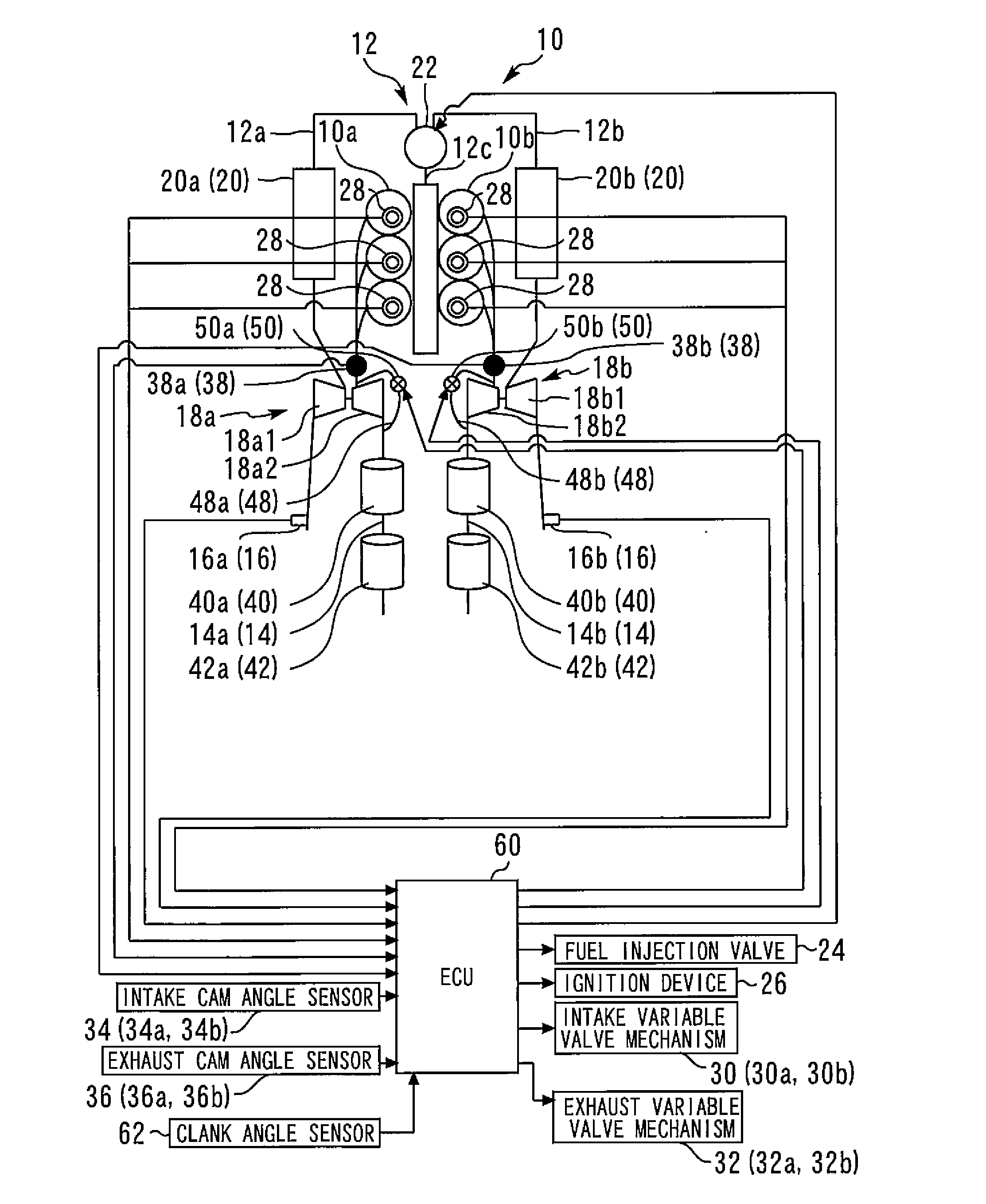
[0017]FIG. 1 is a diagram for illustrating a system configuration of an internal combustion engine 10 according to an embodiment of the present invention. The internal combustion engine 10 is a V gasoline engine, for example. In particular, as shown in FIG. 1, the internal combustion engine 10 includes two banks (cylinder blocks): a first bank 10a including three cylinders and a second bank 10b including three cylinders. In the following description, components provided for the banks 10a and 10b will be denoted by reference numerals with a suffix “a” or “b” to indicate whether the components belong to the bank 10a or 10b, although the suffix “a” or “b” may sometimes be omitted if such differentiation is not needed.

[0018]The internal combustion engine 10 includes an intake air channel 12 that introduces air to each cylinder and an exhaust gas channel 14 through which exhaust gas discharged from each cylinder flows. More specifically...


PUM


Abstract

For each of banks and, the fuel injection amount is changed under a consistent operating condition in which scavenging occurs, and the scavenging amount is calculated from the exhaust gas air fuel ratio at the time when the indicated torque based on the detection value of an in-cylinder pressure sensor is at the maximum. If the scavenging amount differs between the banks, the valve overlapping period of a relevant one of the banks and is controlled to reduce the difference of the scavenging amount between the banks.

Description

BACKGROUND OF THE INVENTION[0001]1. Field of the Invention[0002]The present invention relates to an internal combustion engine and a controller for an internal combustion engine.[0003]2. Background Art[0004]Japanese Patent Laid-Open No. 2013-024203 (hereinafter referred to as Patent Literature 1) discloses a conventional controller for a direct injection internal combustion engine with a supercharger. The conventional controller determines the ratio of the amount of air blowing into the exhaust gas channel to the amount of air passing through the intake valve (referred to as scavenging ratio in Patent Literature 1) by using a physical model (air model) of the response of the air amount in the cylinders to the operation of the throttle that is based on fluid mechanics. Based on the determined scavenging ratio, the controller corrects the target exhaust gas air fuel ratio to calculate the air fuel ratio in the cylinders.[0005]In an internal combustion engine provided with two cylinder...

Claims


Application Information

Patent Timeline
Patent Type & Authority Applications(United States)
IPC IPC(8): F02D41/14F02B37/18F02D41/00F02D41/38F02D13/02
CPCF02D41/1454F02D41/38F02D13/0261F02D13/0242F02D2041/389F02B37/183F02D41/1443F02D2041/001F02D41/0007F02B37/001F02B37/007F02B37/18F02D35/023F02D41/0082F02D41/0085F02D41/40F02D2041/1431Y02T10/12
Inventor TAKAMIYA, FUMIO
Owner TOYOTA JIDOSHA KK
Learn More