Impact Resistant End of Train Device

a technology of end-to-end rail and impact resistance, which is applied in the direction of railway signalling, transportation and packaging, and vehicle signalling indicators, etc., can solve the problems of affecting the internal support of the internal components

Active Publication Date: 2015-09-17
WABTEC HLDG CORP
View PDF3 Cites 1 Cited by
  • Summary
  • Abstract
  • Description
  • Claims
  • Application Information

AI Technical Summary

Benefits of technology

[0007]Accordingly, there is a general need in the art for an impact resistant end of train (EOT) device that incorporates a packing system that protects the internal components of the EOT from vibrations introduced at the mounting to the railcar and from damage incurred from all directions, even when the enclosure of the EOT is damaged or deformed. There is also a general need in the art for such an EOT that incorporates an impact resistant handle.

Problems solved by technology

However, the coupler of the railcar is a very high vibration environment, and because the internal components are rigidly connected to the EOT, a significant amount of vibration is transmitted to the sensitive internal components, resulting in component wear, fatigue, and failure.
Also, EOTs are often subject to rough handling and dropping during transport and mounting by personnel.
This method is effective but has the drawback that any damage to the enclosure of the EOT can disrupt the internal support provided to the internal components.
Further, the shock mounts are not effective equally in all directions and are located at relatively few points, which incur high point loads during an impact.
This type of handle is prone to damage, and may cause permanent deformation and damage to the EOT by transmitting all of the impact energy directly to the enclosure of the EOT when the EOT is dropped or struck.
The handle can be permanently bent or broken, as well as bending or breaking the EOT at the attachment point.

Method used


Image

  • Impact Resistant End of Train Device
  • Impact Resistant End of Train Device
  • Impact Resistant End of Train Device

Examples


Embodiment Construction

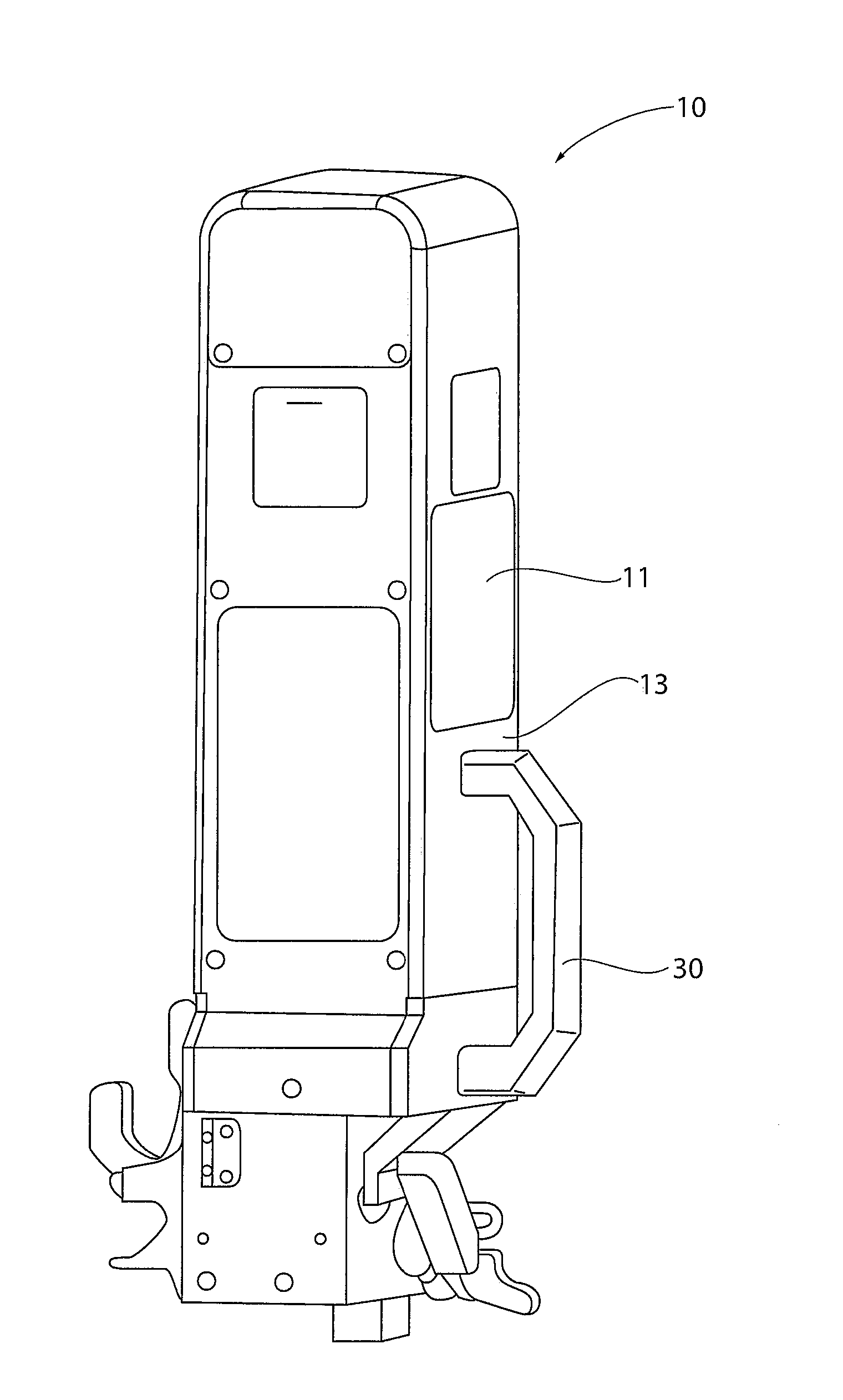
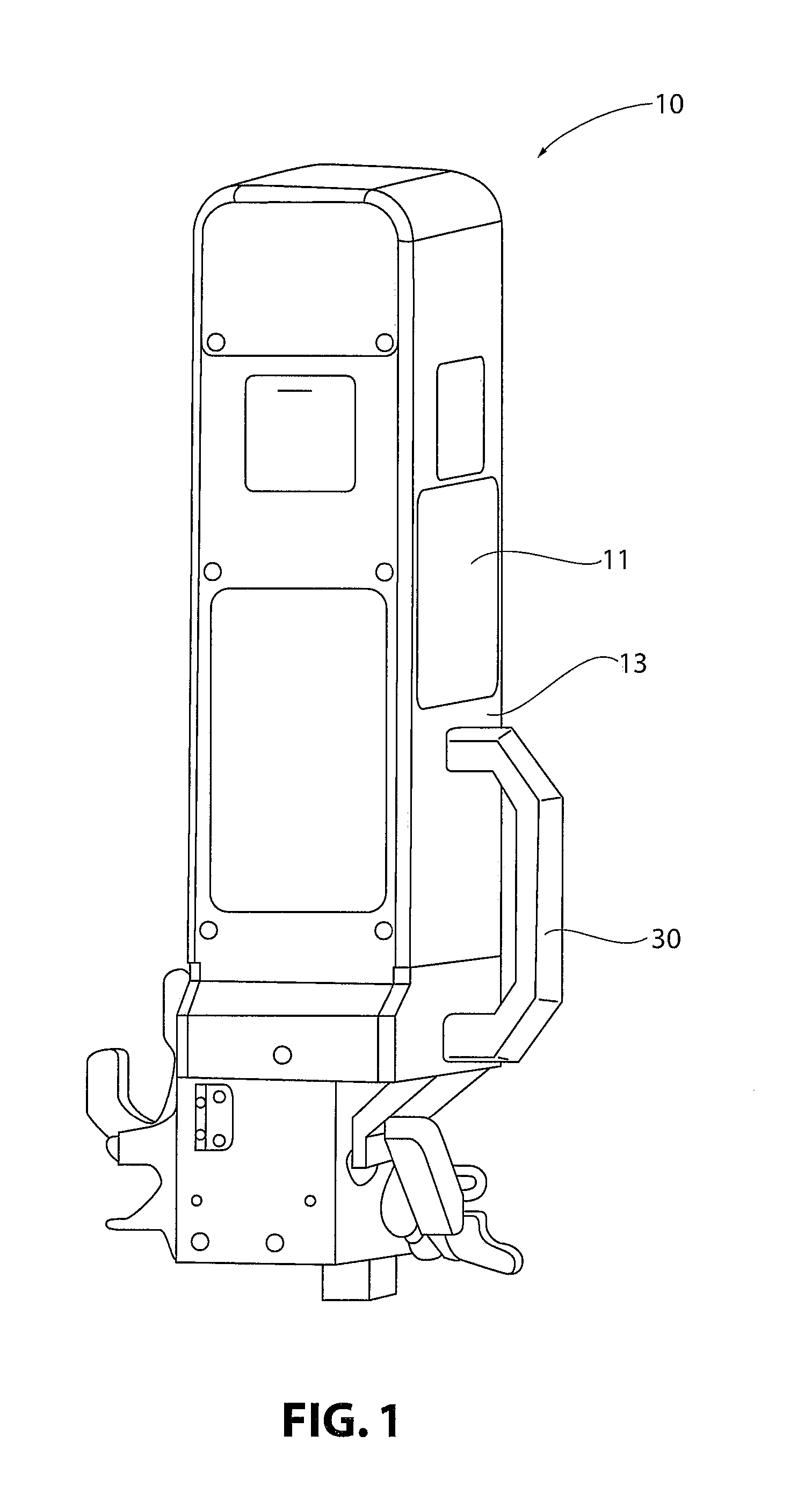
[0041]For purposes of the description hereinafter, the spatial orientation terms, such as “end”, “upper”, “lower”, “right”, “left”, “vertical”, “horizontal”, “top”, “bottom”, “lateral”, “longitudinal” and derivatives thereof, if used, shall relate to the invention as it is oriented in the drawing figures. However, it is to be understood that the invention may assume various alternative variations and step sequences, except where expressly specified to the contrary. It is also to be understood that the specific devices and processes illustrated in the attached drawings, and described in the following specification, are simply exemplary embodiments of the invention and should not be considered as limiting. Hence, specific dimensions and other physical characteristics related to the embodiments disclosed herein are not to be considered as limiting. Further, it is to be understood that the invention may assume various alternative variations and step sequences, except where expressly spe...


PUM


Abstract

An end of train device includes an enclosure having an exterior and a hollow interior housing a plurality of components; and a protective arrangement disposed within the hollow interior of the enclosure and fitted at least partially around at least one component housed within the hollow interior. The protective arrangement defines at least one compartment for the at least one component of the plurality components. The protective arrangement at least partially supports and isolates the at least one component from the enclosure. The device also includes an impact resistant handle disposed on the exterior of the enclosure. The handle is configured to absorb impacts without causing substantial deformation to the enclosure.

Description

BACKGROUND OF THE INVENTION[0001]1. Field of the Invention[0002]The present invention relates to an end of train device (BUT) for connection to the coupler on a railcar. More specifically, the present invention relates to an EOT that includes a protective arrangement fitted around the internal components of the EOT and an impact resistant handle, such that the EOT and its internal components are protected from impacts and vibration.[0003]2. Description of Related Art[0004]End of train devices (EOTs) are generally a combination of electronic, mechanical, and pneumatic components packaged in an enclosure to protect them from damage due to weather, everyday use, and rough handling, which are connected to the coupler on a railcar. The internal components are attached to the housing, and thus the coupler, through a rigid connection to the housing of the EOT. However, the coupler of the railcar is a very high vibration environment, and because the internal components are rigidly connected...

Claims


Application Information

Patent Timeline
Patent Type & Authority Applications(United States)
IPC IPC(8): B61L15/00B61G7/14
CPCB61G7/14B61L15/0054
Inventor GLOYD, D. ANDREWHALOWELL, JOHN E.MCCARY, DAVIDHENNIGES, BENJAMIN
Owner WABTEC HLDG CORP
Why Eureka
Try Eureka