Vehicle Hazard Light Strip

a technology for hazard lights and vehicles, applied in the field of vehicle emergency lighting, can solve the problems of affecting the safety of users, affecting the safety of drivers, and affecting the safety of disabled vehicles,

Inactive Publication Date: 2015-09-10
ANDREWS ERROL
View PDF19 Cites 14 Cited by
  • Summary
  • Abstract
  • Description
  • Claims
  • Application Information

AI Technical Summary

Benefits of technology

The invention is a vehicle hazard light strip that can be easily stored and deployed when needed. It provides sufficient light for users to make repairs to disabled vehicles at night. The light strip is made from materials that are economical and durable. The technical effects of the invention are improved safety for users and ease of use for repairing disabled vehicles.

Problems solved by technology

Motorists with car troubles often have to pull their disabled vehicles off to the side of the road in order to make repairs, inspect the vehicle, or call for help.
While car troubles are inconvenient for the user, the user's problems are magnified when the car troubles occur at night.
It can be dangerous for motorists to pull a disabled vehicle onto the side of the road at night and then exit the vehicle to inspect it and make repairs.
Oncoming cars may have difficulty seeing the motorist and the motorist's disabled vehicle, and thus the motorist is exposed to the risk of being struck by an oncoming car.
In addition to exposure to the risk of being struck by an oncoming vehicle, the low light conditions may also make it difficult for a user to properly inspect a vehicle for problems and to make the necessary repairs.
However, oncoming vehicles may still have trouble seeing the hazard lights at night.
Additionally, the hazard lights do not provide sufficient light for a motorist to inspect their vehicle or make repairs to their vehicle.
Alternatively, a motorist may choose to use a flashlight to inspect the vehicle and make repairs, however the flashlight may not provide sufficient light to illuminate a large area.
The motorist may also find it difficult to make repairs or change a tire while having to hold the flashlight.
The device in Busby does not provide a motorist with sufficient light to make repairs to a disabled vehicle and is instead intended only as a replacement for disabled rear vehicle lights.
McDow does not disclose emergency lights that are capable of providing light to a user making repairs to a disabled vehicle.
The device in Dobert comprises a single light composed of a series of LEDs, and does not disclose an emergency light adapted for use as a light source.
Whiteneck discloses a single light for mounting on a vehicle as a warning light, and does not disclose a plurality of clusters of LED lights suitable for use as a light source.
Thus, Povey et al. does not disclose a light source sufficient to illuminate an area or that can provide sufficient light for a user to make repairs to a vehicle.
Thus, Guerrieri discloses a light source for illuminating the inside of a case or purse and does not disclose a light source sufficient to illuminate a larger area.
Further Guerrieri does not disclose a warning light system adapted for use with automobiles.
Woodbury discloses a series of signal lights to serve as warning lights for other vehicles, but does not disclose an illumination source suited to provide light for performing repairs on a vehicle or for inspecting a vehicle.
Baldwin discloses a hazard light that can be mounted on a vehicle using magnets, but does not disclose a device capable of providing light for a user, nor does Baldwin disclose a series of lights.
Lau discloses a device suitable for providing a warning for a disabled motor vehicle, but does not disclose a lighting system capable of providing a motorist with enough light to make repairs to a disabled vehicle.
However, the prior art does not disclose a combination of a signal light and additional lights sufficient to illuminate a larger area.
Additionally, several devices in the prior art disclose the use of a single light or signal and do not disclose a series of lights or signals.

Method used


Image

  • Vehicle Hazard Light Strip
  • Vehicle Hazard Light Strip
  • Vehicle Hazard Light Strip

Examples


Embodiment Construction

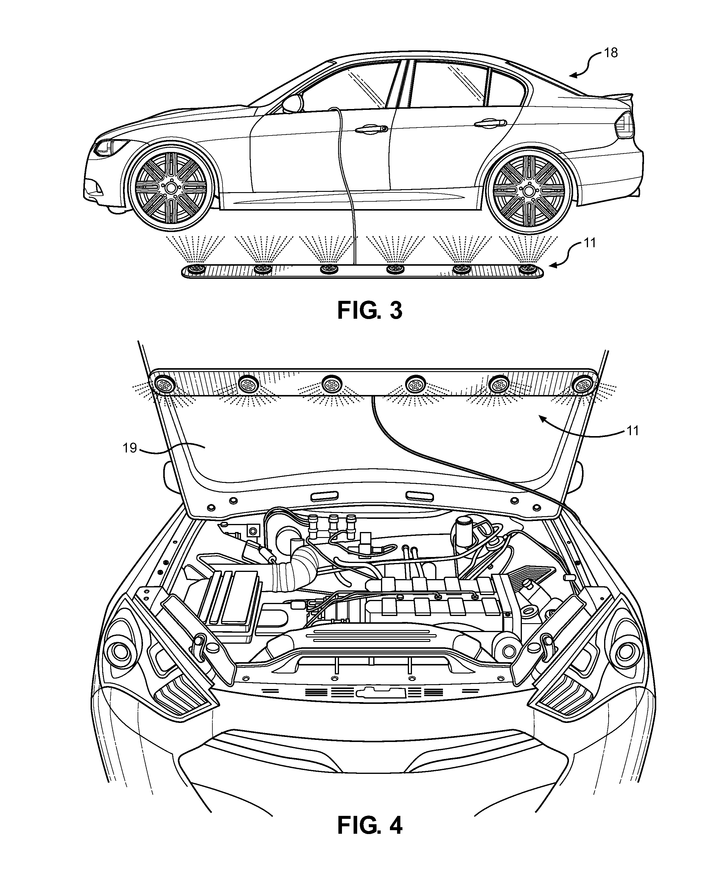
[0030]Reference is made herein to the attached drawings. Like reference numerals are used throughout the drawings to depict like or similar elements of the vehicle hazard light strip. For the purposes of presenting a brief and clear description of the present invention, the preferred embodiment will be discussed as used for assisting a motorist who is pulled over on the side of a dark road with a disabled vehicle. The figures are intended for representative purposes only and should not be considered to be limiting in any respect.

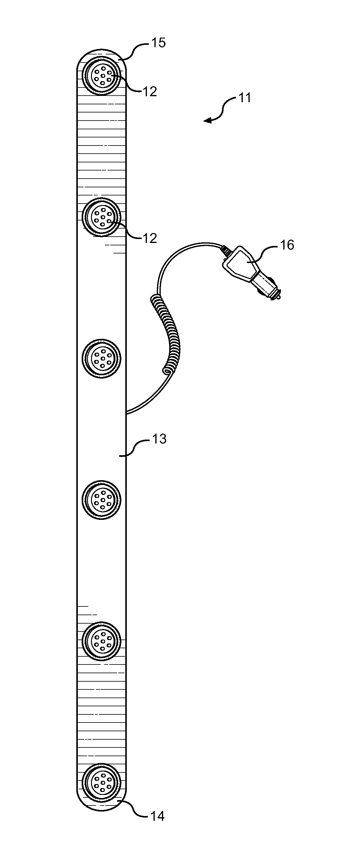
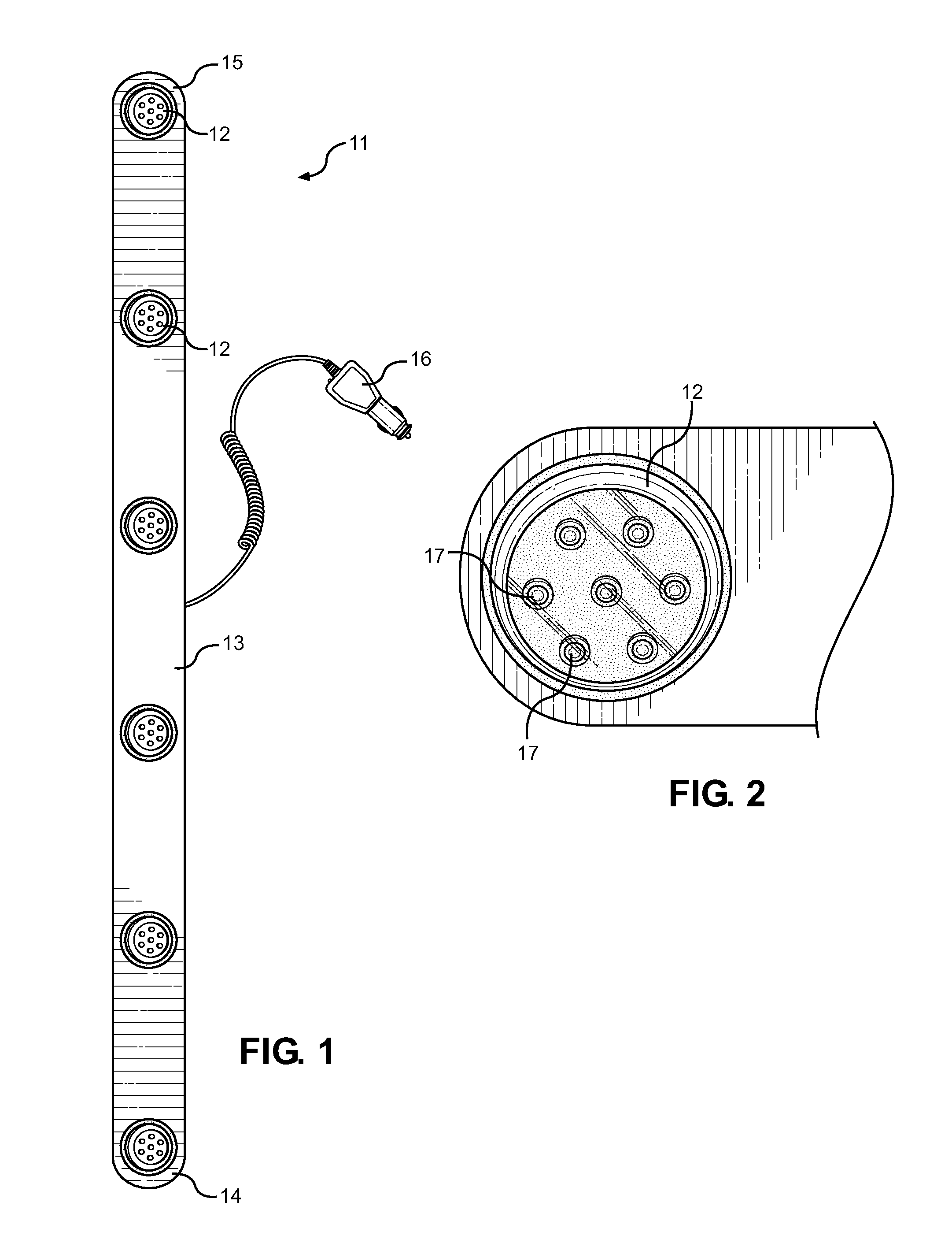
[0031]Referring now to FIG. 1, there is shown a top view of the preferred embodiment of the vehicle hazard light strip of the present invention. The light strip 11 is shown as having one or more clusters 12 of LEDs. In the embodiment shown, the clusters 12 are arranged on a support 13 having a first end 14 and a second end 15. However, other embodiments of the present invention include a support having alternative shapes, such as an L-shape for illuminating ...


PUM


Abstract

Disclosed is an LED light strip for use as a vehicle hazard light system, comprising one or more clusters of LEDs, a control circuit, a power adapter, and a support. The clusters of LEDs comprise a plurality of individual LEDs. Some clusters of LEDs are white in order to provide light, while others are red to serve as warning lights for oncoming vehicles. The clusters of LEDs are disposed on the support and are electrically connected to one another by a control circuit. The control circuit connects the clusters of LEDs to a power adapter designed to plug into a vehicle's power outlet. The LED light strip may further have means for electrically connecting to a rechargeable battery. When a motorist is pulled over with a disabled vehicle, the LED light strip provides ample light for the motorist to make repairs while alerting oncoming traffic to the motorist's presence.

Description

FIELD OF THE INVENTION[0001]The present invention relates to vehicle emergency lighting. More specifically, the present invention describes a vehicle hazard light strip comprising a plurality of clusters of LEDs that is capable of providing light for the user and that alerts approaching vehicles to the user's location.[0002]Motorists with car troubles often have to pull their disabled vehicles off to the side of the road in order to make repairs, inspect the vehicle, or call for help. While car troubles are inconvenient for the user, the user's problems are magnified when the car troubles occur at night. It can be dangerous for motorists to pull a disabled vehicle onto the side of the road at night and then exit the vehicle to inspect it and make repairs. A motorist may exit the vehicle to look for a flat tire, to open the trunk of the car and retrieve tools therefrom, or to open the hood of the car to examine the internal parts of the car. Oncoming cars may have difficulty seeing t...

Claims


Application Information

Patent Timeline
IPC IPC(8): B60Q7/00F21S9/02F21V21/096F21S4/00F21V23/02
CPCB60Q7/00F21S4/008F21S9/024F21V21/096F21V23/02F21V23/06F21S4/28B60Q1/2615B60Q1/52F21Y2115/10B60Q3/88B60Q3/35
Inventor ANDREWS, ERROL
Owner ANDREWS ERROL
Why Eureka
Try Eureka