Thin axial gap motor
a thin motor and axial gap technology, applied in the field of motors, can solve the problems of high cost, and achieve the effect of facilitating the manufacture of thin motors
- Summary
- Abstract
- Description
- Claims
- Application Information
AI Technical Summary
Benefits of technology
Problems solved by technology
Method used
Image
Examples
first preferred embodiment
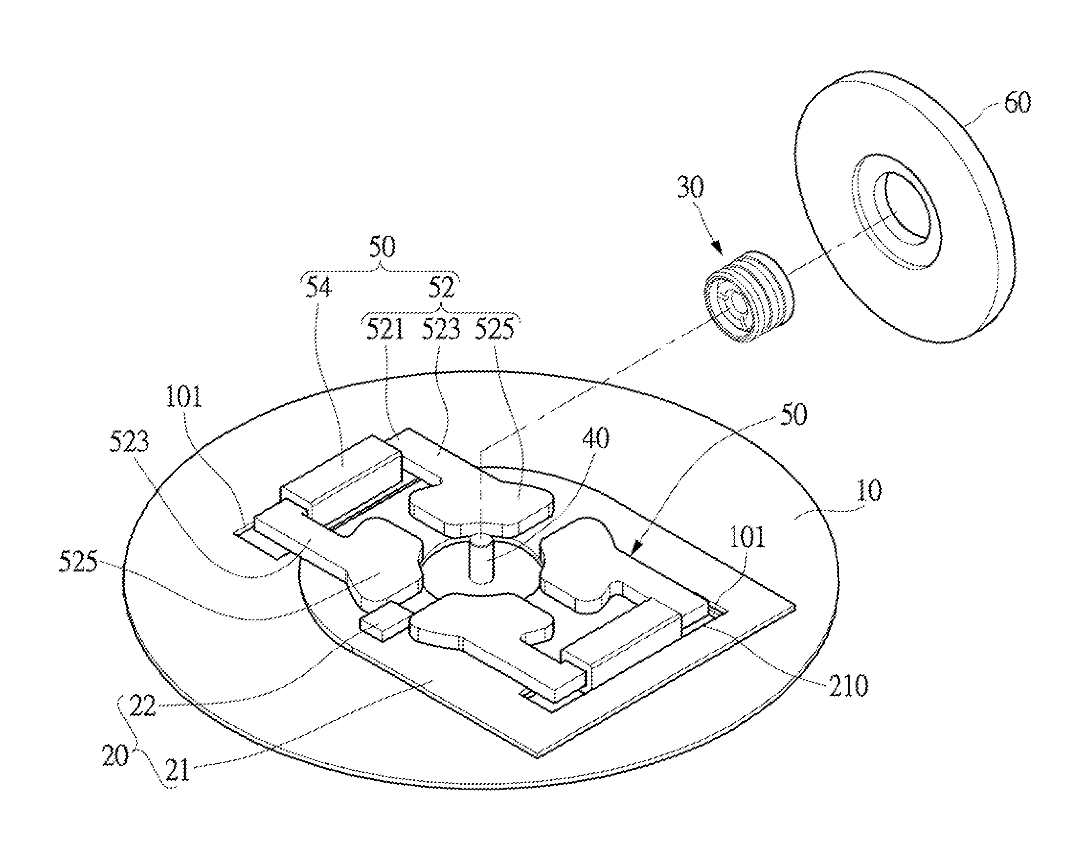
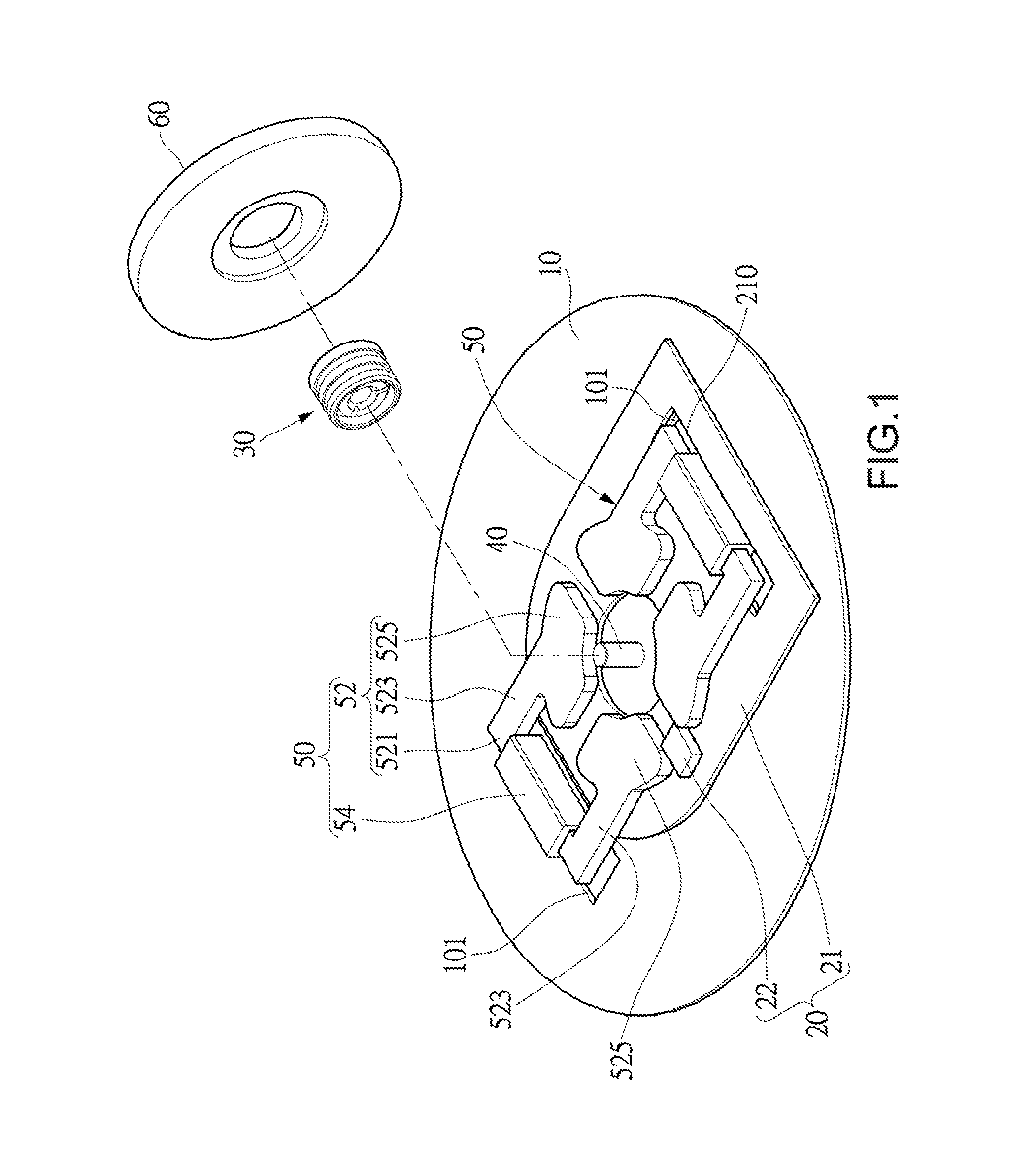
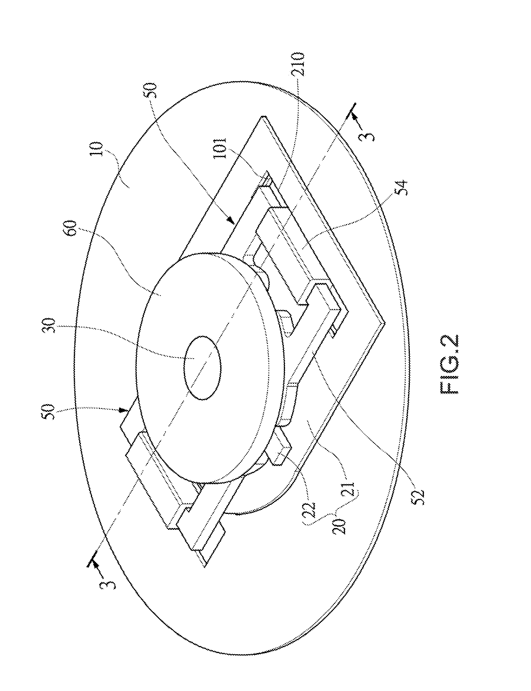
[0039]With reference to FIGS. 1 and 2 for the exploded view and the perspective view of a thin axial gap motor in accordance with the present invention respectively, the thin axial gap motor (hereinafter referred to as “axial gap motor”) comprises a base 10, a circuit unit 20, a bearing housing 30, a spindle 40, a stator module 50 and a rotor module. The design of the present invention is applied to motors, pumps, fans, etc, particularly to any electronic component that requires a small thickness.
[0040]In this preferred embodiment, the base 10 is simply represented by a circular board, primarily serving as a part of a motor casing, and the base 10 may be a metal board or a plastic board.
[0041]The circuit unit 20 is installed on the base 10. The circuit unit 20 includes a circuit board 21, and at least one electronic component 22 installed on the circuit board 21.
[0042]In this preferred embodiment, the spindle 40 is vertically fixed to the base 10, and the bottom of the spindle 40 is...
second preferred embodiment
[0056]With reference to FIG. 6 for a perspective exploded view of a thin axial gap motor in accordance with the second preferred embodiment of the present invention, the stator module 50a of this preferred embodiment is also comprised of two symmetrical permeable frames 52a and two symmetrical windings 54a to provide a 4-slot 4-pole arrangement. Each permeable frame 52a includes two substantially straight external arm parts 521 installed opposite to each other, and a winding 54a wound around each external arm part 521, and both ends of each external arm part 521 are coupled to a connecting arm part 523, and each connecting arm part 523 is coupled to an induced magnetic part 527, 529, and the induced magnetic parts 527, 529 are arranged into a circular ring shape.
[0057]With reference to FIG. 7 for a schematic view of a stator motor with a permanent magnet removed from the stator motor as depicted in FIG. 6, a separating groove g is formed between any two adjacent induced magnetic par...
third preferred embodiment
[0059]With reference to FIGS. 11 and 12 for a perspective exploded view and a planar sectional view of a thin axial gap motor in accordance with the third preferred embodiment of the present invention respectively, the difference between this preferred embodiment and the second preferred embodiment resides on that each permeable frame 52b of the stator module 50b includes two substantially straight external arm parts 521 installed opposite to each other, and a connecting arm part 523 is coupled separately to both ends of each external arm part 521, and a winding 54b is wound around each connecting arm part 523, and each connecting arm part 523 is coupled to an induced magnetic part 527, 529, and the plurality of induced magnetic parts 527, 529 are arranged into a circular ring shape.
[0060]To further reduce the height of the motor, a wire containing hole 210b is formed on the circuit board 21 of the circuit unit 20 for accommodating a part of the winding 54b. In addition, an opening ...
PUM
 Abstract
Description
Claims
Application Information
 - R&D
- Intellectual Property
- Life Sciences
- Materials
- Tech Scout
- Unparalleled Data Quality
- Higher Quality Content
- 60% Fewer Hallucinations
Browse by: Latest US Patents, China's latest patents, Technical Efficacy Thesaurus, Application Domain, Technology Topic, Popular Technical Reports.
© 2025 PatSnap. All rights reserved.Legal|Privacy policy|Modern Slavery Act Transparency Statement|Sitemap|About US| Contact US: help@patsnap.com


