
Apparatus and method for producing core rod of optical fiber

a technology of optical fiber and core rod, which is applied in the field of apparatus and method for producing core rod of optical fiber, can solve the problems of difficult to achieve a complex refractive index profile, affecting the quality the physical and chemical properties of the outer cladding are not so good as those of the core rod, so as to reduce the cost of optical amplifier, reduce the cost of maintenance, and long distance transmission

Active Publication Date: 2015-08-27
ZHONGTIAN TECH ADVANCED MATERIALS CO LTD
View PDF3 Cites 3 Cited by
  • Summary
  • Abstract
  • Description
  • Claims
  • Application Information

AI Technical Summary

Benefits of technology

The invention relates to a new method for producing optical fibers for long distance transmission. The method involves combining a core layer and an inner cladding layer produced by different apparatuses and methods. The resulting fiber has a deeply depressed refractive index profile with ultra-low water peaks and is suitable for long distance transmission. The cost of optical amplifiers and repeaters for long distance transmission is thus reduced. The method also allows for the production of ultra-low refractive index and ultra-low water peaks fibers that are suitable for long distance transmission.

Problems solved by technology

In order to control the production cost of the optical fiber, the fraction of the impurities (especially the moisture) in the material of the outer cladding layer is usually higher than that in the core rod, and the physical and chemical properties of the outer cladding are not so good as those of the core rod.
Furthermore, deposition of the outer cladding layer is usually performed in a high temperature that affects the quality of the core rod.
Therefore, it is difficult to achieve a complex refractive index profile (e.g., that of an inner cladding layer in shape of concave and convex in turn) using traditional VAD method.
This disadvantage limits the application of traditional VAD method to only production of single model optical fiber having a simple refractive index profile without deep depression, such as G652, G657A1 / G657A2, etc.

Method used


Image

  • Apparatus and method for producing core rod of optical fiber
  • Apparatus and method for producing core rod of optical fiber
  • Apparatus and method for producing core rod of optical fiber

Examples


Embodiment Construction

[0037]To further illustrate the invention, an apparatus and a method of producing a depressed-cladding core rod of an ultra-low water peak optical fiber are described below. It should be noted that the following examples are intended to describe and not to limit the invention.

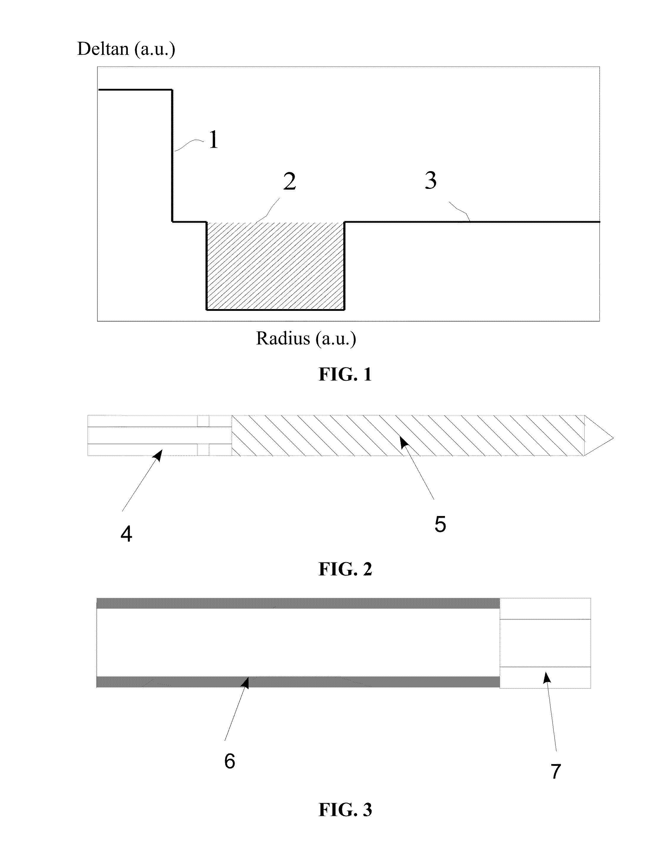
[0038]Detailed description of embodiments of the invention will be given below in conjunction with accompanying FIGS. 1-5.

[0039]As shown in FIGS. 2-5, the apparatus of producing a depressed-cladding core rod of an ultra-low water peak optical fiber includes a core rod component, an inner cladding casing component, a high temperature heat source 8, chucks 9, a rotary joint 10, an external gas pipe 11, and a pressure controlling pipe 12.

[0040]As shown in FIG. 2, the core rod component is produced by fusing and splicing the core layer rod 5 and the hollow shaft 4 together. A plurality of vents is drilled on the hollow shaft 4 at the end near the core layer rod 5. As shown in FIG. 3, the inner cladding casing compo...


PUM

PropertyMeasurementUnit
Temperatureaaaaaaaaaa

Abstract

An apparatus and a method for producing a depressed-cladding core rod of an ultra-low water peak optical fiber, the apparatus including a core rod component, an inner cladding casing component, a high temperature heat source, chucks, a rotary joint, an external gas pipe, and a pressure controlling pipe. The core rod component is produced by fusing and splicing a core layer rod and a first hollow shaft together. The inner cladding casing covers the outside of the core layer rod. The inner cladding casing component is produced by fusing and splicing an inner cladding casing and a second hollow shaft together. These two hollow shafts are clamped in two chucks of a glass lathe. A high temperature heat source is arranged outside the inner cladding casing.

Description

CROSS-REFERENCE TO RELATED APPLICATIONS[0001]This application is a continuation-in-part of International Patent Application No. PCT / CN2013 / 072603 with an international filing date of Mar. 14, 2013, designating the United States, now pending, and further claims priority benefits to Chinese Patent Application No. 201210546942.0 filed Dec. 17, 2012. The contents of all of the aforementioned applications, including any intervening amendments thereto, are incorporated herein by reference. Inquiries from the public to applicants or assignees concerning this document or the related applications should be directed to: Matthias Scholl P. C., Attn.: Dr. Matthias Scholl Esq., 245 First Street, 18th Floor, Cambridge, Mass. 02142.BACKGROUND OF THE INVENTION[0002]1. Field of the Invention[0003]The present invention relates to an apparatus and a method for producing a depressed-cladding core rod of an ultra-low water peak optical fiber. The method avoids contamination of the interface and the insi...

Claims


Application Information

Patent Timeline
IPC IPC(8): C03B37/012C03C25/68
CPCC03B37/01211C03B2203/22C03C25/68C03B37/0126C03B37/01248C03B37/01257C03B2203/23C03C23/0075
Inventor JIANG, XINLIXU, XIKAICHEN, JINWENZHOU, HUIQIAN, BENHUA
Owner ZHONGTIAN TECH ADVANCED MATERIALS CO LTD
Learn More