
Valve controlled high frequency oscillatory ventilation

Active Publication Date: 2015-08-27
MAQUET CRITICAL CARE
View PDF4 Cites 2 Cited by
  • Summary
  • Abstract
  • Description
  • Claims
  • Application Information

AI Technical Summary

Benefits of technology

The patent proposes a breathing apparatus that can provide high-frequency ventilation (HFO) at frequencies of 20 Hz or more. The apparatus needs to have an inspiration valve that can quickly go from its most open position to a fully closed position. The patent describes a ventilator called the SERVO-i ventilator that meets this requirement and can be easily adapted for HFO ventilation by adding a computer program to a control unit of the ventilator. The patent also discusses the issue of reverse flow in the expiratory line and proposes various means to prevent or limit it, such as an expiration valve or a length of tubing in the expiratory line. The expiration valve is closed during the initial phases of the expiration to prolong the active expiration of the patient. The patent also mentions the use of a controllable expiration valve that can be actively closed to prevent reverse flow at the end of the expiration phases.

Problems solved by technology

There are several drawbacks associated with HFO ventilators according to prior art.
Piston and loudspeaker based HFO ventilators are sometimes noisy due to the high frequency movement of the piston or diaphragm.
Furthermore, the need for oscillation generators in form of pistons, loudspeakers or ejectors increases the cost and complexity of the ventilators

Method used


Image

  • Valve controlled high frequency oscillatory ventilation
  • Valve controlled high frequency oscillatory ventilation
  • Valve controlled high frequency oscillatory ventilation

Examples


Embodiment Construction

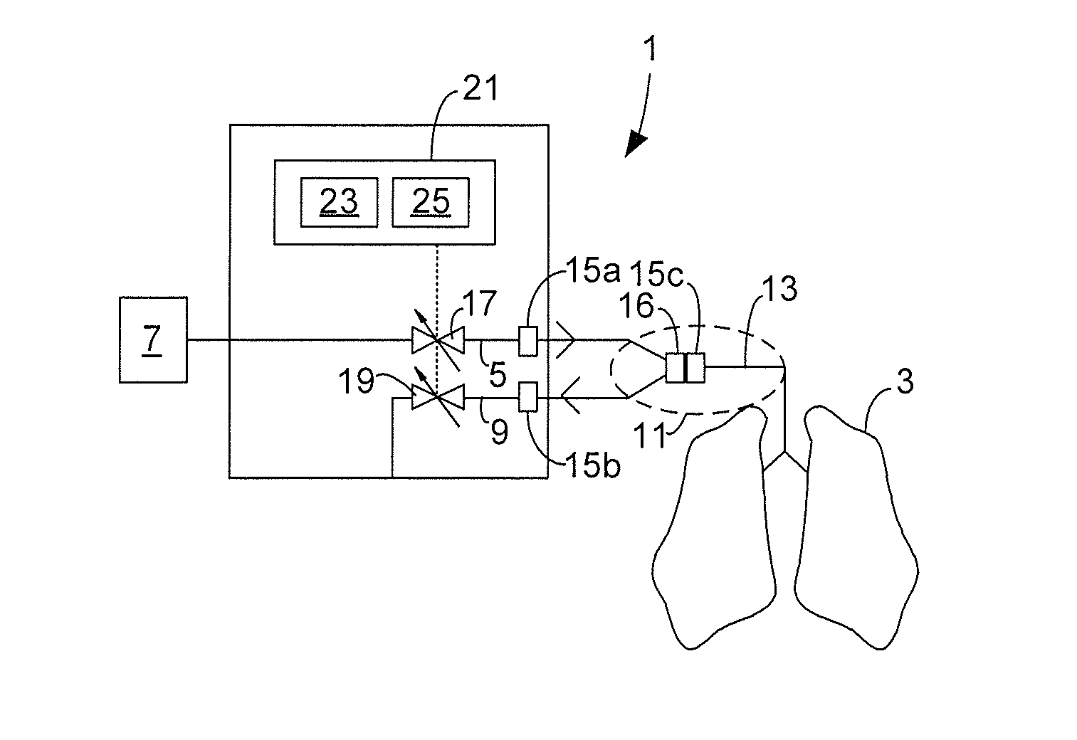
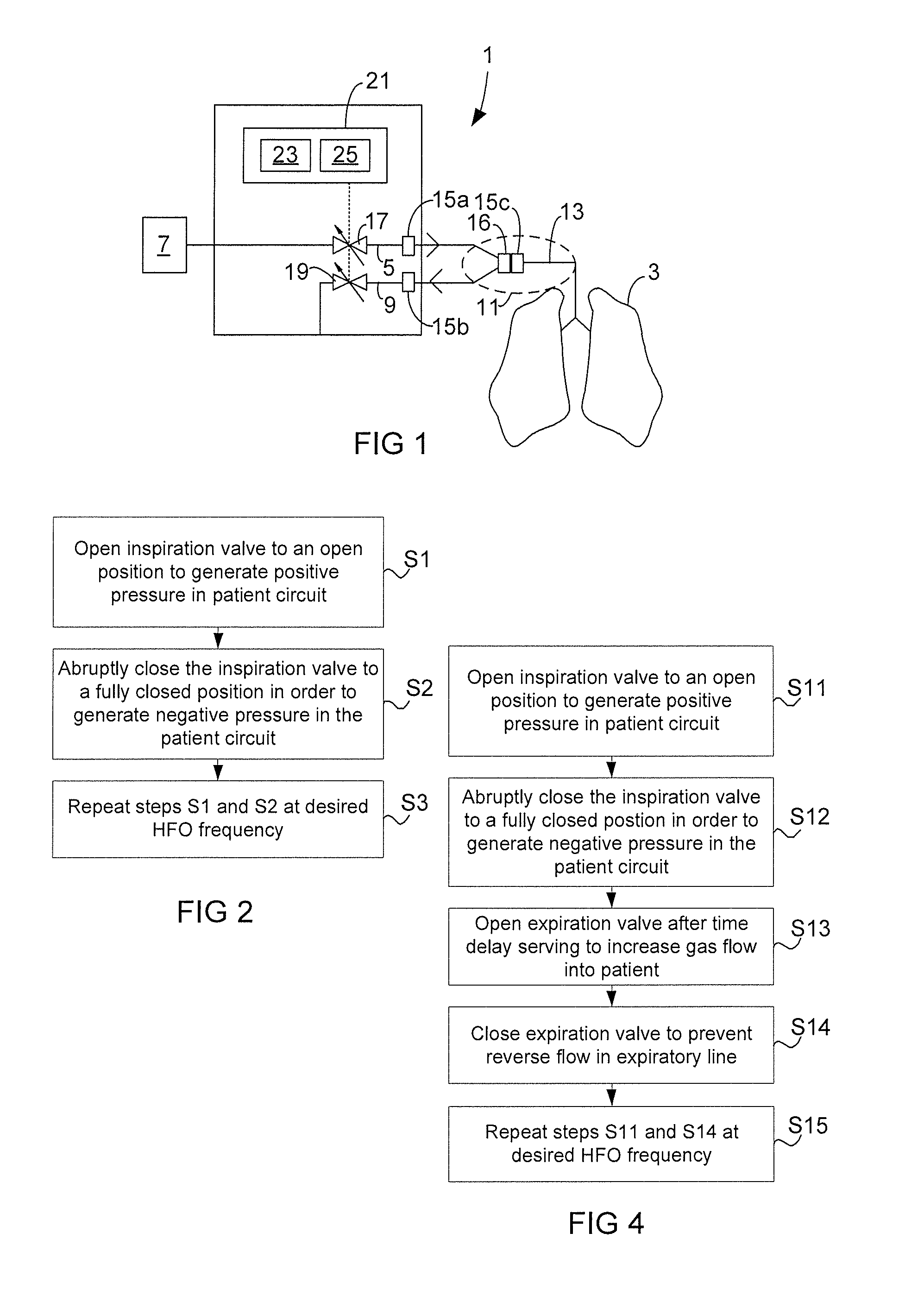
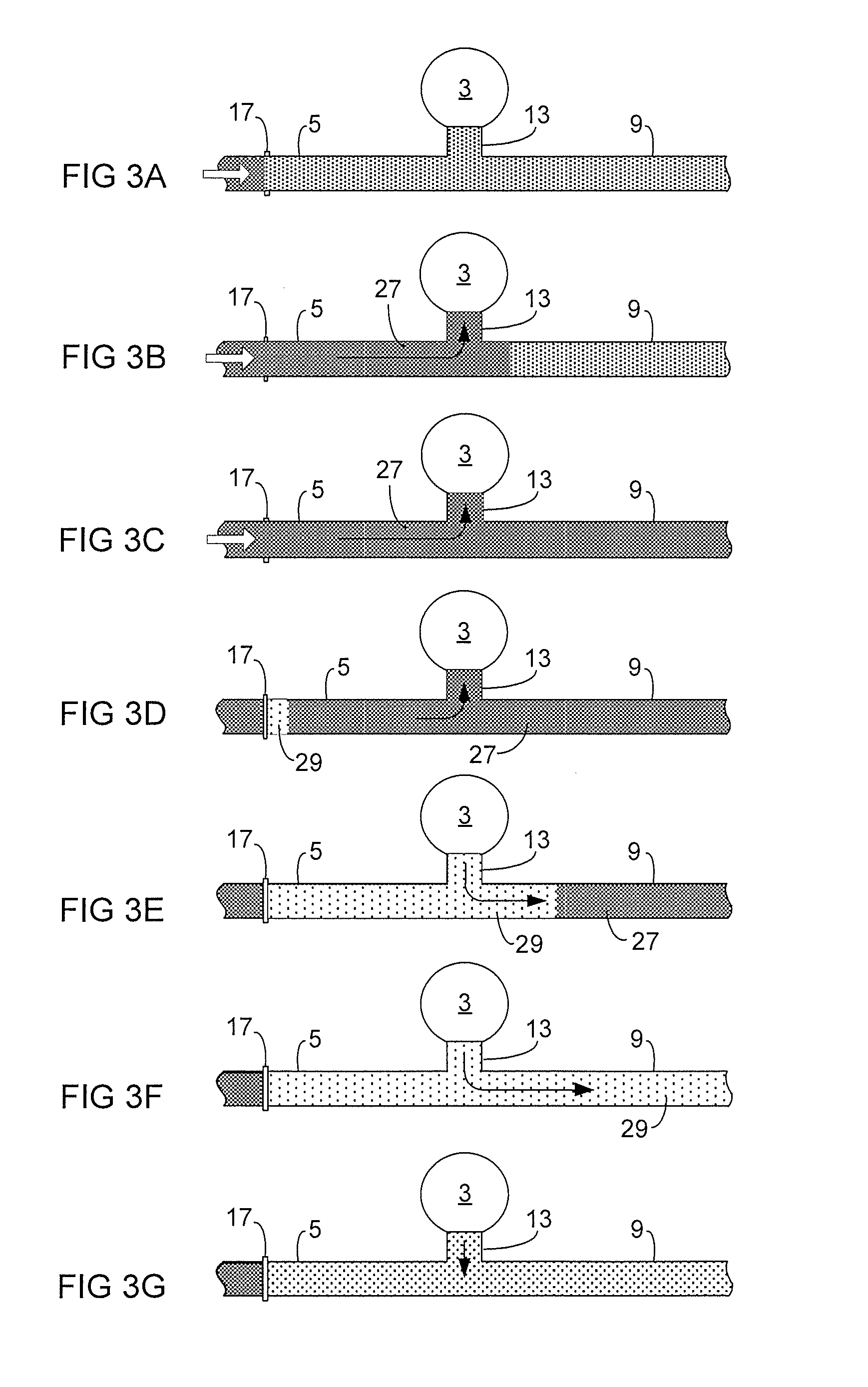
[0043]FIG. 1 illustrates a breathing apparatus 1 for providing high frequency oscillatory (HFO) ventilation to a patient 3, according to an exemplary embodiment of the invention. The breathing apparatus 1 is a ventilator comprising an inspiratory line 5 for conveying pressurised breathing gas from at least one gas source 7 to the patient 3, and an expiratory line 9 for conveying expiration gas away from the patient 3 to atmosphere or a scavenging system (not shown). The inspiratory line 5 and the expiratory line 9 are connected to each other and to the patient 3 via a patient connector 11 comprising a common line 13 for conveying the breathing gas and the expiration gas to and from the patient. The patient connector 11 further comprises a so called Y-piece connecting the inspiratory line 5 and the expiratory line 9 with the common line 13. The inspiratory line 5, expiratory line 9, and the patient connector 11 together form a patient circuit of the breathing apparatus 1.

[0044]The br...


PUM


Abstract

A breathing apparatus provides high frequency oscillatory ventilation [HFO] to a patient by supplying breathing gas to the patient according to an oscillating pressure profile oscillating between a positive pressure and a negative pressure. The breathing apparatus has a patient circuit including an inspiratory line for conveying breathing gas to the patient and an expiratory line for conveying gas away from the patient, and an inspiration valve for regulating a flow of pressurised breathing gas into the inspiration line, and a control computer that controls the inspiration valve. The control computer operates to cause the oscillating pressure profile by controlling the inspiration valve to oscillate between a top flow position in which the flow of breathing gas through the inspiration valve assumes a top flow value, and a minimum flow position in which the flow through the inspiration valve assumes a minimum flow value.

Description

TECHNICAL FIELD[0001]The present invention relates to a breathing apparatus, method, and a computer program for providing high frequency oscillatory ventilation to a patient.BACKGROUND[0002]High frequency oscillatory ventilation (HFO or HFOV) is normally used to deliver small tidal volumes of breathing gas to neonatal patients who cannot be adequately ventilated using conventional ventilation. During inspiration, an overpressure is generated in the breathing circuit of the ventilator to push the breathing gas into the patient, and, during expiration, an underpressure in the breathing circuit serves to pull gas out of the airways of the patient. The application of a pressure profile oscillating between a positive and a negative pressure in relation to surrounding pressure (atmospheric pressure) makes both inspiration and expiration “active”, which minimizes the risk of gas trapping in the patient.[0003]HFO ventilation is typically carried out in frequency range of 5-20 Hz with a tida...

Claims


Application Information

Patent Timeline
IPC IPC(8): A61M16/20A61M16/00
CPCA61M16/204A61M16/0003A61M2205/52A61M2016/0027A61M2205/3334A61M16/0057A61M16/0096A61M16/12A61M2016/0021A61M2016/0036A61M2016/0039A61M2016/0042A61M16/0009A61M16/205A61M16/206
Inventor LINDSTROM, STEFANTROILI, CARL ERIKHALLBACK, MAGNUS
Owner MAQUET CRITICAL CARE
Learn More