Method and apparatus for distributing firewall rules

a firewall and rule technology, applied in the field of firewall rules, can solve the problems of failing to provide security among the machines behind the choke point, and reducing the processing speed of the firewall engine, so as to achieve faster search speed, faster processing, and small size

Active Publication Date: 2015-08-20
NICIRA
View PDF8 Cites 34 Cited by
  • Summary
  • Abstract
  • Description
  • Claims
  • Application Information

AI Technical Summary

Benefits of technology

The patent text describes a method of creating firewall rules for virtual machines (VMs) that can be easily specified, without slowing down the processing of the rules by the firewall engine. The method allows for the distribution of the firewall rules to firewall-enforcing devices that may connect to the VMs, even before the VMs have been instantiated on the host. The method also allows for the efficient control of specifying whether the rule is to be done at the source or destination of a packet, and can be used to easily create firewall rules for a single tenant or a single logical network in a multi-tenant environment. Overall, the method results in faster processing and better performance by using non-bloated firewall rule tables with fewer rules.

Problems solved by technology

Also, they fail to provide security among the machines behind the choke point.
Hence, they have the same disadvantages as hardware firewalls, i.e., they are choke points for the network traffic and fail to provide security for the intra network traffic (i.e., for virtual machines behind the choke point).
Also, this approach causes rule bloat at VNIC level firewall table, which, in turn, reduces the processing speed of the firewall engine.
This approach also does not have the ability to control whether rule processing is done at source or destination for intra VM traffic.
The current VNIC-level approaches are also not truly multi-tenant solution because, in order to achieve multi-tenancy, a user has to create multiple firewall contexts (or multiple firewall tables) at the controller level.

Method used


Image

  • Method and apparatus for distributing firewall rules
  • Method and apparatus for distributing firewall rules
  • Method and apparatus for distributing firewall rules

Examples


Embodiment Construction

[0027]In the following detailed description of the invention, numerous details, examples, and embodiments of the invention are set forth and described. However, it will be clear and apparent to one skilled in the art that the invention is not limited to the embodiments set forth and that the invention may be practiced without some of the specific details and examples discussed.

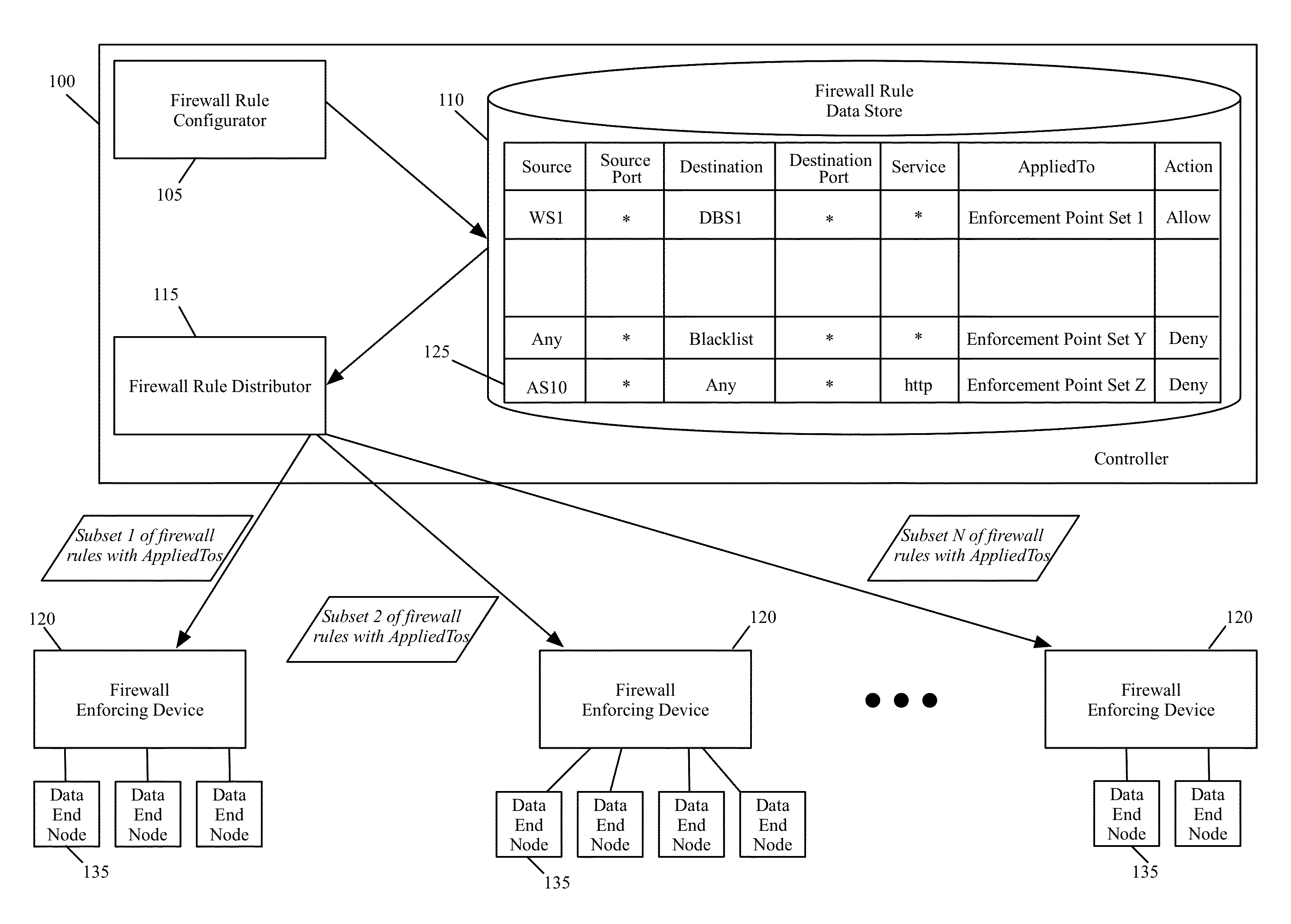
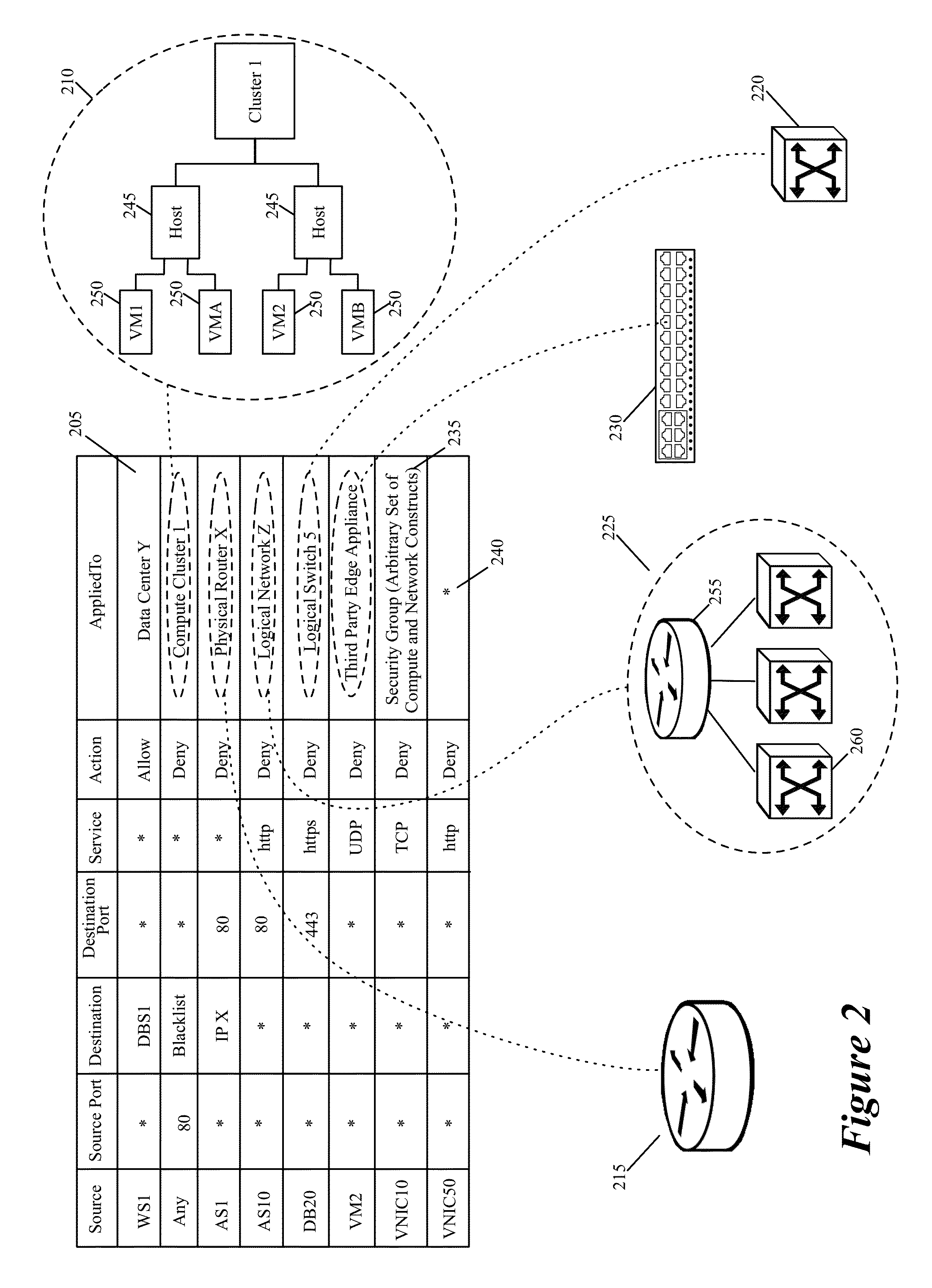
[0028]Some embodiments of the invention provide a novel method for specifying firewall rules. In some embodiments, the method provides the ability to specify for a particular firewall rule, a set of network node locations (called a set of enforcement points below) at which the particular firewall should be enforced. To provide this ability, the method of some embodiments adds an extra tuple (referred to below as the AppliedTo tuple) to a firewall rule. This added AppliedTo tuple lists the set of enforcement points at which the firewall rule has to be applied (i.e., enforced).

[0029]FIG. 1 illustrates a controll...


PUM


Abstract

Some embodiments of the invention provide a novel method for specifying firewall rules. In some embodiments, the method provides the ability to specify for a particular firewall rule, a set of network nodes (also called a set of enforcement points below) at which the particular firewall should be enforced. To provide this ability, the method of some embodiments adds an extra tuple (referred to below as the AppliedTo tuple) to a firewall rule. This added AppliedTo tuple lists the set of enforcement points at which the firewall rule has to be applied (i.e., enforced).

Description

BACKGROUND[0001]Typically, firewall rule definitions include the following five tuples: source, source port, destination, destination port, and service (or application), in addition to an action value. Each tuple specifies a set of identifiers that provide acceptable values for the tuple. This holds true for most of the firewalls in use today, including hardware-based firewalls and software-based firewalls. Hardware firewalls can be used to protect both physical as well as virtual machines (VMs). Hardware firewalls have a number of drawbacks. For instance, hardware firewalls are often choke point solutions, as they each serve as a single choke point for enforcing all firewall rules because all the traffic has to pass through them. Also, they fail to provide security among the machines behind the choke point.[0002]Software firewalls can be implemented as either a service node firewall or VNIC (virtual network interface card) level firewall. The service-node firewalls are similar to t...

Claims


Application Information

Patent Timeline
Patent Type & Authority Applications(United States)
IPC IPC(8): H04L29/06H04L47/20
CPCH04L63/0245H04L63/0263H04L63/02H04L63/20
Inventor BANSAL, KAUSHALMASUREKAR, UDAYSRINIVASAN, ARAVINDSHAH, SHADABMASKALIK, SERGE
Owner NICIRA
Why Eureka
Try Eureka