Sampling and Analytical Platform for the Remote Deployment of Sensors

a technology of sampling and analytical platform, applied in the field of environmental monitoring, can solve problems such as inability to easily adapt to many environmental analyses through systems

Inactive Publication Date: 2015-08-20
BURGE SCOTT RUSSELL
View PDF7 Cites 14 Cited by
  • Summary
  • Abstract
  • Description
  • Claims
  • Application Information

AI Technical Summary

Benefits of technology

[0029]The invention disclosed does not use flow-through cells, but interchangeable sample chambers where volumes of reagents, standards, and samples may be precisely introduced into the sample chambers to perform the required analysis. Water level sensors are employed in each sample chamber to deliver a precise volume of sample, reagent or standard. The analyses or calibrations are performed in isolation after all the solutions are injected into the sample chamber. The sample chamber may be stirred, and temperature adjusted by heating or cooling, after being introduced in the sample chamber.
[0030]This separation of the sensors, sample chambers, and calibration modules from the sampling/analytical platform is not described in the prior art or literature. The prior art and literature describe elaborate systems containing all the sample chambers, sensors, sampling components, and methods of calibration formed into a single unit. The prior a

Problems solved by technology

Many of the prior art citations and current commercialized instruments use rigid

Method used


Image

  • Sampling and Analytical Platform for the Remote Deployment of Sensors
  • Sampling and Analytical Platform for the Remote Deployment of Sensors
  • Sampling and Analytical Platform for the Remote Deployment of Sensors

Examples


Embodiment Construction
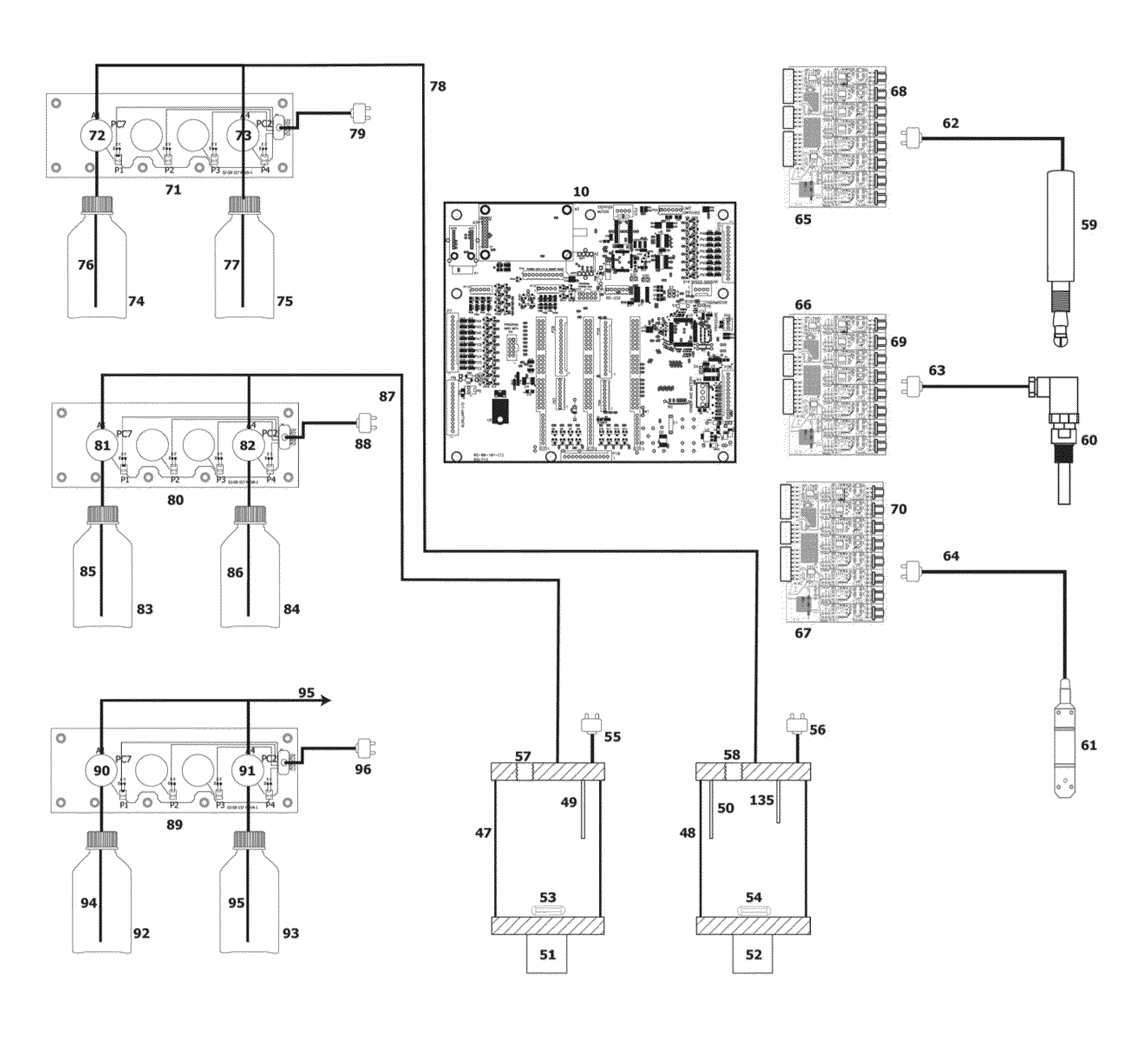
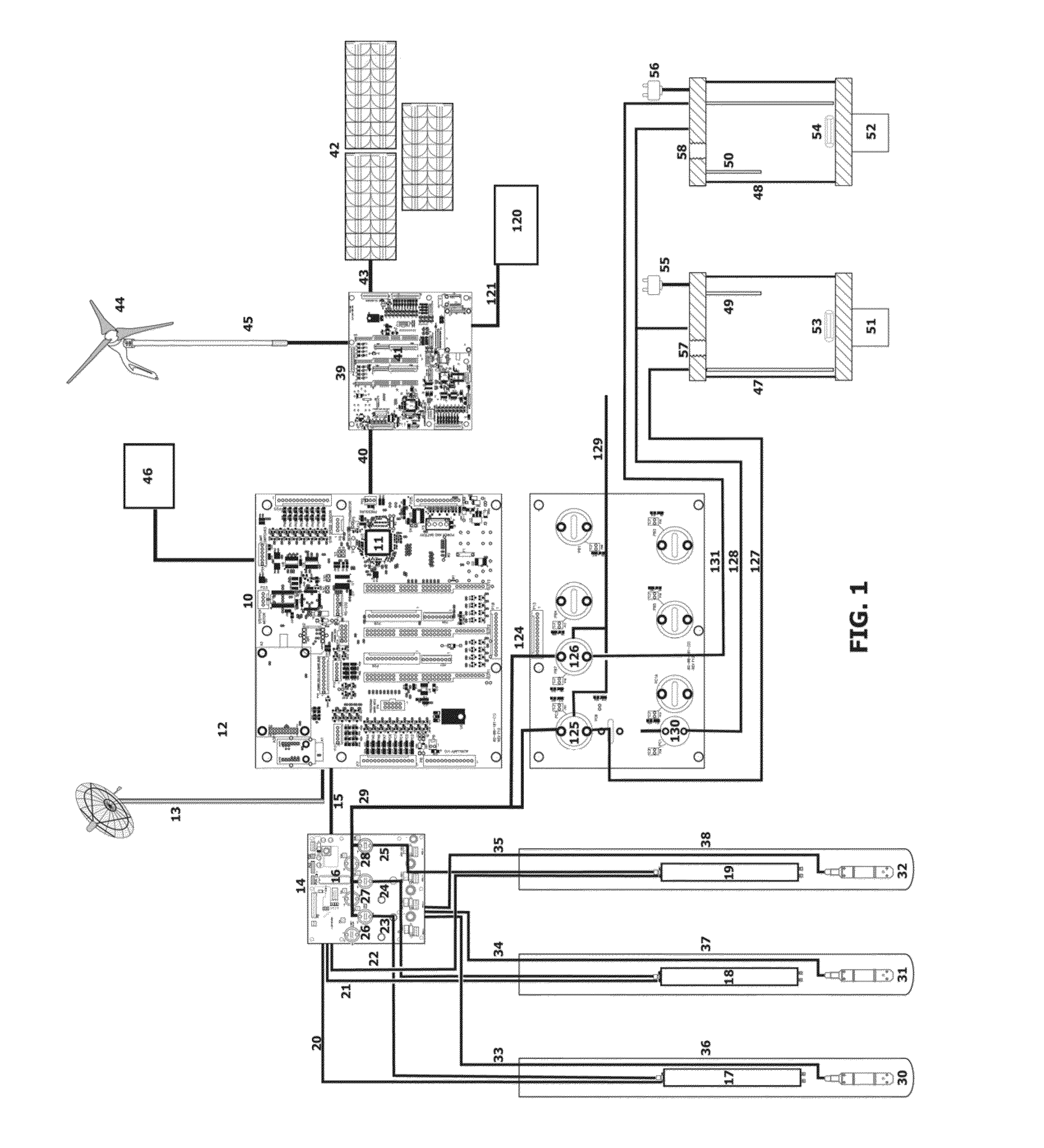
[0037]FIG. 1

[0038]FIG. 1 illustrates the overall monitoring system. A main control board 10 is the central component of the entire monitoring system. A control microprocessor 11 and communications module 12 are incorporated on the main control board 10. The communication module 12 is connected to an antenna 13. Transmission of signals may be performed using radio telemetry, cellular or satellite methods. A pump control board 14 is connected to the board 10 using a control cable 15. The hoard 14 incorporates a microprocessor 16 to control the operation of various sampling, methods. Multiple selection valves 26, 27, 28 are incorporated on the board 14.

[0039]The sampling methods supported by the board 14 include peristaltic pumps and submersible pumps that are directly inserted into monitoring wells 36, 37, 38. The board 14 is connected to multiple pumps 17, 18, 19 located within the multiple monitoring wells 36, 37, 38 by multiple cables 20, 21, 22. The pumps 17, 18, 19 located within...


PUM


Abstract

An automated microprocessor-controlled monitoring system for the sampling and analysis of environmental contamination has independent multiple sample chambers 47, 48. The sample chambers are populated with multiple analytical sensors 59, 60, 61, Multiple water level sensors 49, 50, 135 located in the sample chambers are capable of determining the volume of sample, or standard, introduced into the individual sample chambers. The monitoring system is standardized with independent calibration modules 7L 80, 89 to support the analytical sensors in the sample chambers. This configuration of a monitoring system allows a “plug and play” configuration with all analytical sensors capable of standardization. The system anticipates the incorporation of future sensing methodologies through its flexible design. The disclosed system is capable of operating multiple pumps 17, 18, 19 and measuring the water levels 30, 31, 32 in multiple monitoring wells 36, 37, 38 allows for the automated acquisition of data for slug, aquifer, and tracer tests. Other embodiments are described and illustrated.

Description

CROSS-REFERENCE TO RELATED APPLICATIONS[0001]Reference is made to our Provisional Application No. 61 / 766745 filed Feb. 20, 2013 entitled “Sampling and Analytical Platform for Remote Deployment of Sensors” by the present inventors.BACKGROUND OF THE INVENTION[0002]1. Field of Invention[0003]The field of environmental monitoring has many chemical parameters and environmental contaminants to be measured for the purposes of environmental compliance. The environmental contaminants to be monitored will vary based on the industry or site to be assessed. The cost of developing monitoring systems tar each type of industry or contaminated site is prohibitive, therefore, an automated monitoring system that can be configured using a series of independent chambers with analytical sensors and calibration modules combined into a package that will measure many of the important parameters of a facility would have the ability to attract a significant share of the environmental monitoring market.[0004]...

Claims


Application Information

Patent Timeline
IPC IPC(8): G01N33/18G01J3/50G01N27/333G01N35/10G01N27/30
CPCE02D1/06G01N1/16G01N33/1826G01N33/182G01N33/18G01N27/333G01N2033/0093Y02A20/20G01N35/1065G01J3/50G01N2035/00306
Inventor BURGE, SCOTT RUSSELL
Owner BURGE SCOTT RUSSELL
Why Eureka
Try Eureka