
Windshield mounting assembly

a technology for mounting assemblies and windscreens, which is applied in the direction of rotorcraft, clear-view screens, vessel construction, etc., can solve the problems of reducing the available area of pilot visibility, difficult integration of mounting frames, and limited load transfer,

Active Publication Date: 2015-08-20
AIRBUS HELICOPTERS DEUT GMBH
View PDF2 Cites 6 Cited by
  • Summary
  • Abstract
  • Description
  • Claims
  • Application Information

AI Technical Summary

Benefits of technology

The technical effect of this patent is that the inventive windshield mounting assembly can be used with a wide range of vehicles, including helicopters, aircrafts, cars, and vessels. The assembly is attached to the vehicle frame with screws, making it easy to replace. The mounting frame does not interfere with visibility and is more compact than conventional designs. The bearing strength of the mounting frame is much higher than that of the windshield, so high loads can be transferred from the frame to the vehicle frame without stressing the windshield. The recesses at the edges of the windshield reduce stress concentration and facilitate a higher transfer of loads.

Problems solved by technology

However, depending on an underlying application of a given windshield, i.e. an associated vehicle frame, different maximum load requirements are applied to the windshield and thus, or in addition, specific geometric constraints must be considered when designing the windshield and an associated mounting frame.
However, such a mounting frame reduces the available area of visibility of the pilot.
Furthermore, such a mounting frame is often difficult to integrate because of underlying geometric constraints.
This limited load transfer is, however, not sufficient for sustaining large loads such as bird strike, especially on comparatively large helicopter windows.
However, some materials that are usually used to embody windshields have a comparatively low bearing strength and / or are sensitive to local stress concentration and notches (e.g. Polycarbonate).
Thus, providing windshields that are made up of such materials with holes that are arranged in the area of an outer edge thereof would weaken the windshields and lead to an increased risk of damage or breakage of such windshields.
Therefore, such windshields are not suitable for use with helicopters having comparatively high maximum load requirements, especially if bird-strike proof is required.
However, in this case replacement of the windshield can be difficult and time-consuming if the windshield is damaged or broken in operation.

Method used


Image

  • Windshield mounting assembly
  • Windshield mounting assembly
  • Windshield mounting assembly

Examples


first embodiment

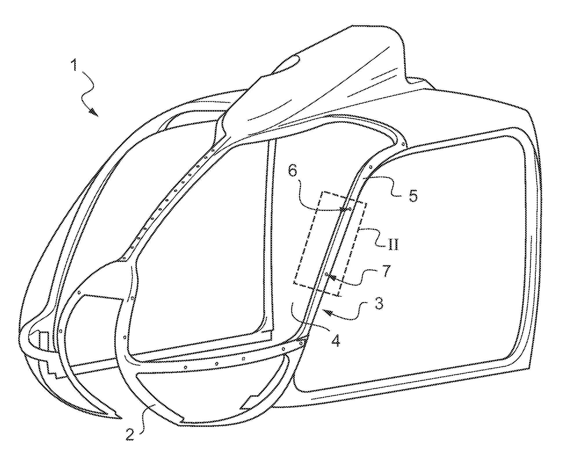
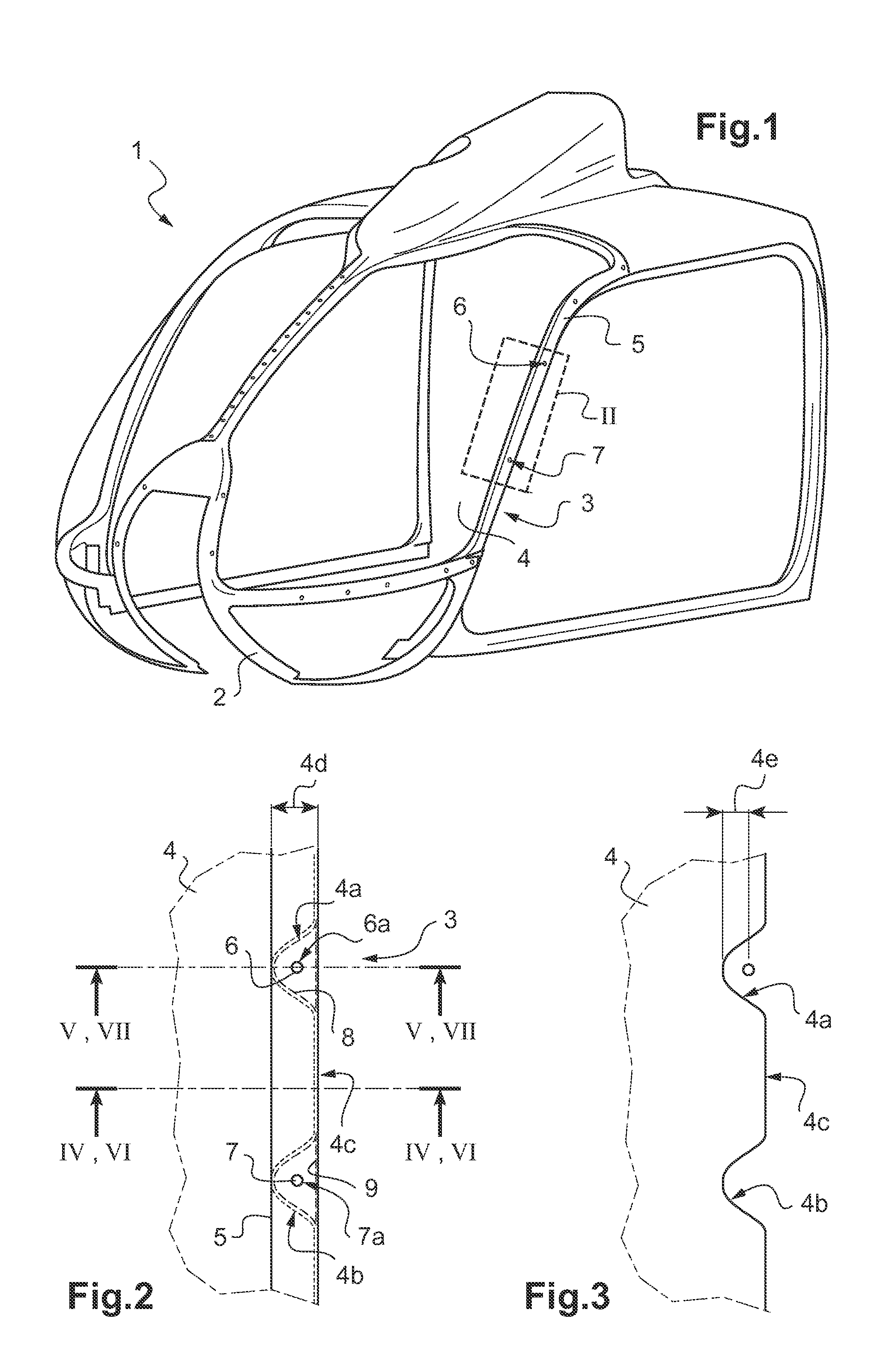
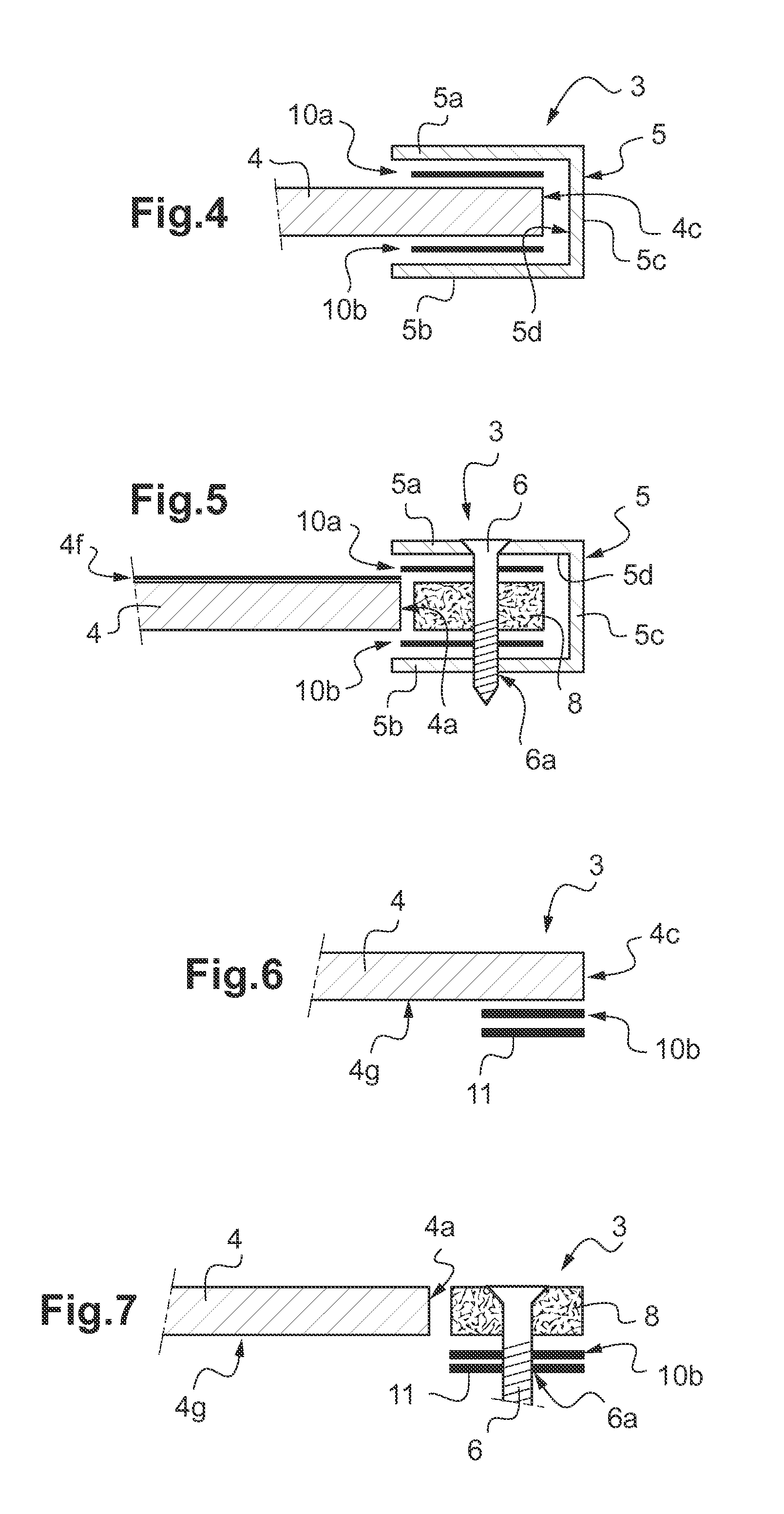
[0064]FIG. 4 shows the windshield mounting assembly 3 of FIG. 1 and FIG. 2 with the windshield 4 and the mounting frame 5 in a region beyond the two lateral recesses 4a, 4b of the windshield 4. the mounting frame 5 is at least partially U-shaped in cross section having two frame legs or side walls 5a, 5b that are interconnected via a leg connecting wall 5c. These side walls 5a, 5b and the connecting wall 5c define an inner frame groove 5d that is adapted to receive the single edge 4c of the windshield 4.

[0065]Preferably, a bonding interface 10a, 10b is arranged at least partially between the single edge 4c of the windshield 4 and the mounting frame 5. This bonding interface 10a, 10b attaches the single edge 4c to the mounting frame 5 and is e.g. at least partially realized by a soft glue, such as a PU glue.

[0066]By way of example, the bonding interface 10a, 10b comprises two layers 10a, 10b of PU glue. A first layer 10a is illustratively provided between the side wall 5a of the mou...

second embodiment

[0071]FIG. 7 shows the windshield mounting assembly 3 of FIG. 1 and FIG. 2 with the windshield 4 and the mounting frame 11 according to FIG. 6, in the region of the lateral recess 4a of the windshield 4. As described above with reference to FIG. 2, the lateral recess 4a is filled with the spacer 8 and the mounting frame 11 and this spacer 8 comprise the frame fastener receiving opening 6a, wherein the frame fastener 6 is exemplarily arranged.

[0072]Preferably, the spacer 8 is bonded to the mounting frame 11 by the bonding interface 10b, i.e. by the layer 10b of PU glue. This layer 10b and, thus, the bonding interface 10b, preferably covers at least the spacer 8 and, preferentially, the complete single edge 4c of the windshield 4 of FIG. 2, at least over a length that is equal or greater than the depth 4d of FIG. 2 of the lateral recess 4a.

[0073]It should be noted that modifications and variations to the above described embodiments are within the common knowledge of the person skille...


PUM


Abstract

A windshield mounting assembly, comprising a windshield that is adapted to be arranged on an associated vehicle frame, the windshield comprising at least one edge that is provided with at least one lateral recess; at least one mounting frame that is attached to the windshield and adapted for mounting of the windshield to the associated vehicle frame, the mounting frame comprising at least one fastener receiving opening that is arranged in the region of the lateral recess and adapted to receive an associated frame fastener; and a bonding interface that is arranged at least partially between the edge of the windshield and the mounting frame, the bonding interface attaching the edge to the mounting frame.

Description

CROSS REFERENCE TO RELATED APPLICATION[0001]This application claims priority to European patent application No. EP 14 400009.8 filed on Feb. 18, 2014, the disclosure of which is incorporated in its entirety by reference herein.BACKGROUND OF THE INVENTION[0002](1) Field of the Invention[0003]The invention is related to a windshield mounting assembly with a windshield that is adapted to be arranged on an associated vehicle frame and at least one mounting frame that is attached to said windshield, said windshield mounting assembly comprising the features of claim 1.[0004](2) Description of Related Art[0005]Vehicle frames can be provided with one or more windshields that are configured to embody aerodynamically formed windows on a given front of corresponding vehicles. These windshields are provided in order to protect occupants of the corresponding vehicles from wind and potentially flying debris, such as insects and dust.[0006]In order to allow for an easy replacement of a windshield ...

Claims


Application Information

Patent Timeline
IPC IPC(8): B64C1/14B64C27/04
CPCB60J1/004B62J17/04B63B19/02B64C1/1492B64C27/04B60J1/007
Inventor MARKMILLER, JOHANNES
Owner AIRBUS HELICOPTERS DEUT GMBH
Learn More