Method of associating tire pressure control apparatuses to wheel positions

a control apparatus and wheel technology, applied in the field of associating the position of the tire pressure control apparatus, can solve the problems of reducing the lifespan of the tire pressure control device, and achieve the effect of increasing the speed of the vehicl

Active Publication Date: 2015-08-20
HUF BAOLONG ELECTRONICS BRETTEN GMBH
View PDF8 Cites 5 Cited by
  • Summary
  • Abstract
  • Description
  • Claims
  • Application Information

AI Technical Summary

Benefits of technology

[0036]There are advantages when the tire pressure control device has the possibility to select the duration of the first time interval Δt1 in which in the tire pressure control device the detected measurand is subjected to a low pass filtering, and / or the duration of the second time interval Δt2 depending on speed or depending on the rotation speed of the respective wheel, and namely such that the duration of the first time interval Δt1 and / or the duration of the second time interval Δt2 decreases with increasing speed of the vehicle. This adaptation to the speed of the vehicle or respectively to the rotation speed of the respective wheel can take place in stages or continuously. Particularly, the adaptation takes place in stages, in particular in two or three stages distributed over the entire speed range or respectively the rotation speed range of the wheel. Thereby, it can be achieved that the angular displacement of the tire pressure control device between the end of the measurement interval and the transmission moment, i.e. the angle about which the wheel rotates further in the second time interval Δt2, is restricted to the range of 0° to 180°. This restriction can be utilized e.g. so that the tire pressure control device transmits the second measured values M2 twice to the central unit, and namely for the first time at the end of the second time interval Δt2 and for the second time after a further rotation of the wheel and of the tire pressure control device about less than one revolution, in particular after a further rotation of the wheel about a half revolution of the wheel. In this way, it can be ensured that at least one of the two transmittals of one and the same measured value M2 takes place from a position of the tire pressure control device which is favourable for reception by the central unit. This contributes to the allocation method according to the invention being able to be terminated substantially more quickly than competing methods in the prior art.
[0037]A central unit may be used in which for each wheel position more than one identification can be, and particularly is, stored. This makes it possible to store the identifications for at least two sets of wheels, e.g. for a set of summer wheels and for a set of winter wheels, so that with a changeover from summer wheels to winter wheels the identifications of the exchanged tire pressure control devices are already present in the central unit.

Problems solved by technology

This method has the disadvantage that the tire pressure control devices must send twice for each allocation attempt, also for allocation attempts without effect, when namely not all tire pressure control devices show different angular offsets.
Allocation attempts without effect waste the energy which is stored in a non-exchangeable battery of the tire pressure control device and thereby reduce its lifespan.

Method used


Image

  • Method of associating tire pressure control apparatuses to wheel positions
  • Method of associating tire pressure control apparatuses to wheel positions
  • Method of associating tire pressure control apparatuses to wheel positions

Examples


Embodiment Construction

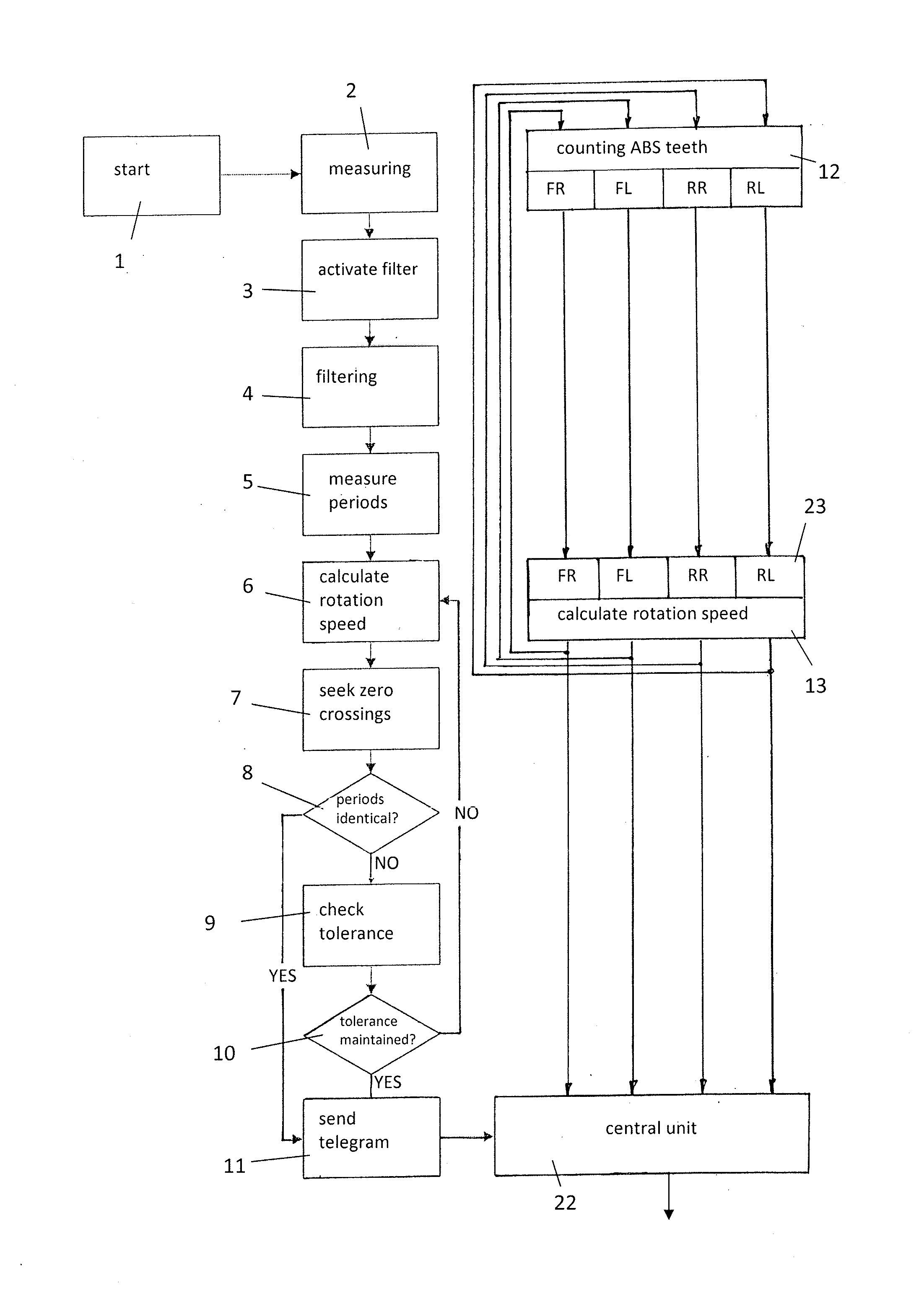
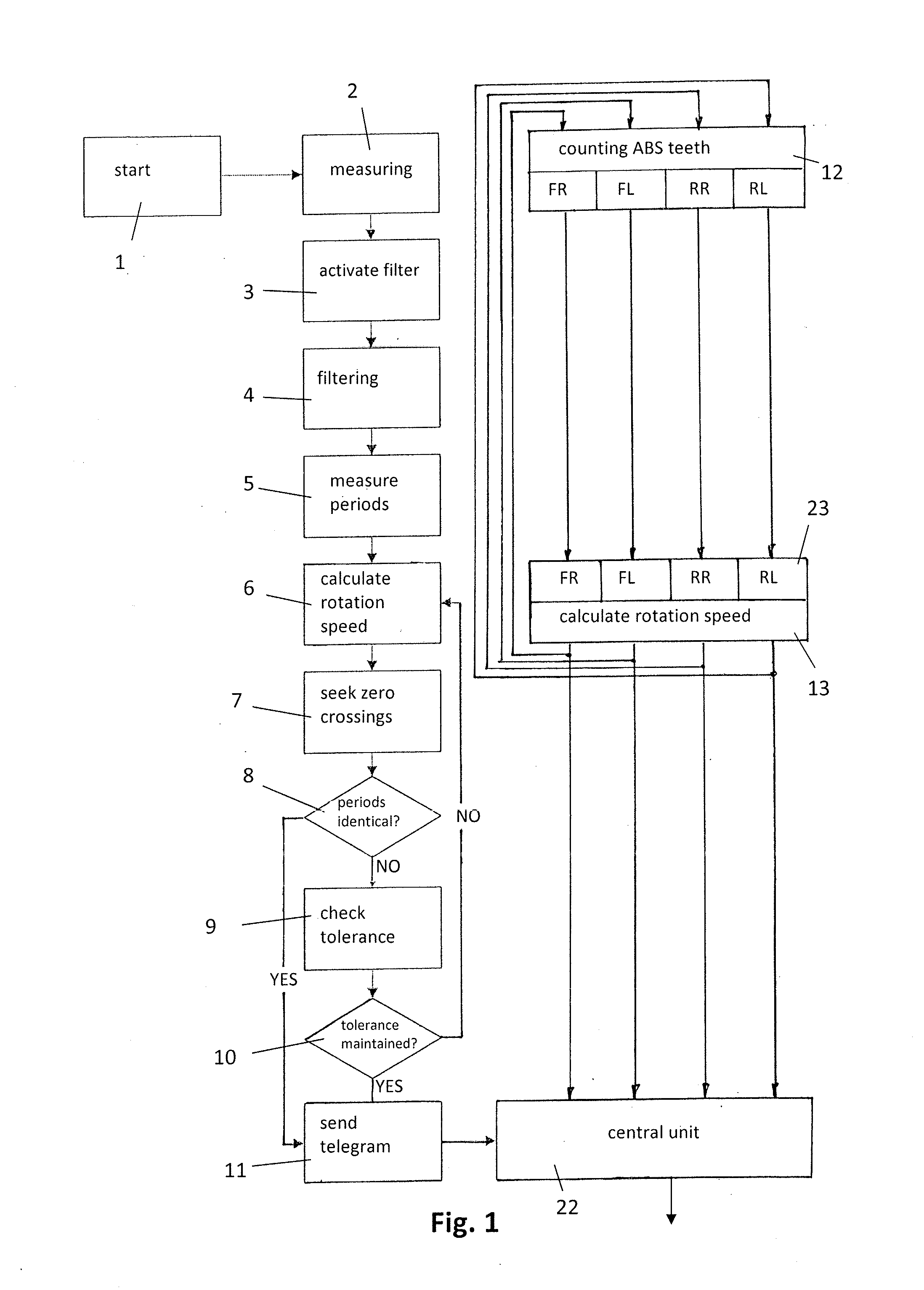
[0053]According to FIG. 1, the method begins in the tire pressure control device of a wheel which is mounted on a vehicle, in step 1 with a start signal which is generated in the tire pressure control device itself, e.g. in that an acceleration sensor establishes that the wheel is rotating after it was not able to establish a movement for a predetermined duration, e.g. more than half an hour. Triggered by the start signal, in a step 2 the acceleration occurring at the tire pressure control device is begun to be measured continuously and the acceleration measured values are begun to be stored pointwise respectively for the duration of a predetermined number of periods.

[0054]The pointwise storage can take place so that an analog acceleration signal delivered by the acceleration sensor is scanned pointwise, in particular in constant time intervals, and the discrete acceleration values ascertained in this way for a predetermined number of periods of the acceleration signal are stored in...


PUM


Abstract

Tire pressure control devices include first sensors to deliver repeatedly a measured value M1 for the rotation speed of the wheel. A measurand, from which the rotation speed of the associated wheel can be derived, is detected in a pointwise manner by means of a second sensor over a predetermined rotation angle φ of the wheel as a function of time, is subjected to a low pass filtering in a subsequent first time interval Δt1 and from the filtered development of the measurand a second measured value M2 is determined, which is a measurement for the rotation speed or respectively for the angular speed of the associated wheel. Each tire pressure control device transmits at the end of a second time interval Δt2 the second measured value M2 together with an identification of the tire pressure control device to a central unit. Comparing M1 and M2 determines wheel position.

Description

CROSS-REFERENCE TO RELATED APPLICATIONS[0001]This continuation application claims priority to PCT / EP2013 / 072991 filed on Nov. 5, 2013 which was published as WO 2014 / 072269 A1 and also the German application number 10 2012 110 689.4 filed on Nov. 8, 2012, the contents of which are fully incorporated herein with these references.DESCRIPTIONField of the Invention[0002]The invention relates to an automatic method for the allocating of tire pressure control devices of a tire pressure control system of a vehicle to the different positions of a number of wheels of the vehicle.BACKGROUND OF THE INVENTION[0003]From DE 197 34 323 B4 an allocation method is known, according to which a revolution sensor, e.g. an acceleration sensor, provided in a tire pressure control device, sends a telegram to a central unit in a first time interval at a particular angular position of the wheel, and in a second time interval sends a second telegram to the central unit at an angular position of the wheel diffe...

Claims


Application Information

Patent Timeline
Patent Type & Authority Applications(United States)
IPC IPC(8): B60C23/04G01P3/00G01P15/00
CPCB60C23/04G01P3/00G01P15/00B60C23/0416B60C23/0488B60C23/0489
Inventor WAGNER, MARKUSBRAND, PETERALEXANDER, MARKUS
Owner HUF BAOLONG ELECTRONICS BRETTEN GMBH
Why Eureka
Try Eureka