
Releasable substrate on a carrier

a technology of releasable substrates and carriers, applied in the direction of transportation and packaging, other domestic articles, chemistry apparatus and processes, etc., can solve the problems of low dimensional and/or thermal stability of substrates, alignment issues, adhesion should not prevent,

Active Publication Date: 2015-08-20
NEDERLANDSE ORG VOOR TOEGEPAST-NATUURWETENSCHAPPELIJK ONDERZOEK (TNO)
View PDF3 Cites 24 Cited by
  • Summary
  • Abstract
  • Description
  • Claims
  • Application Information

AI Technical Summary

Benefits of technology

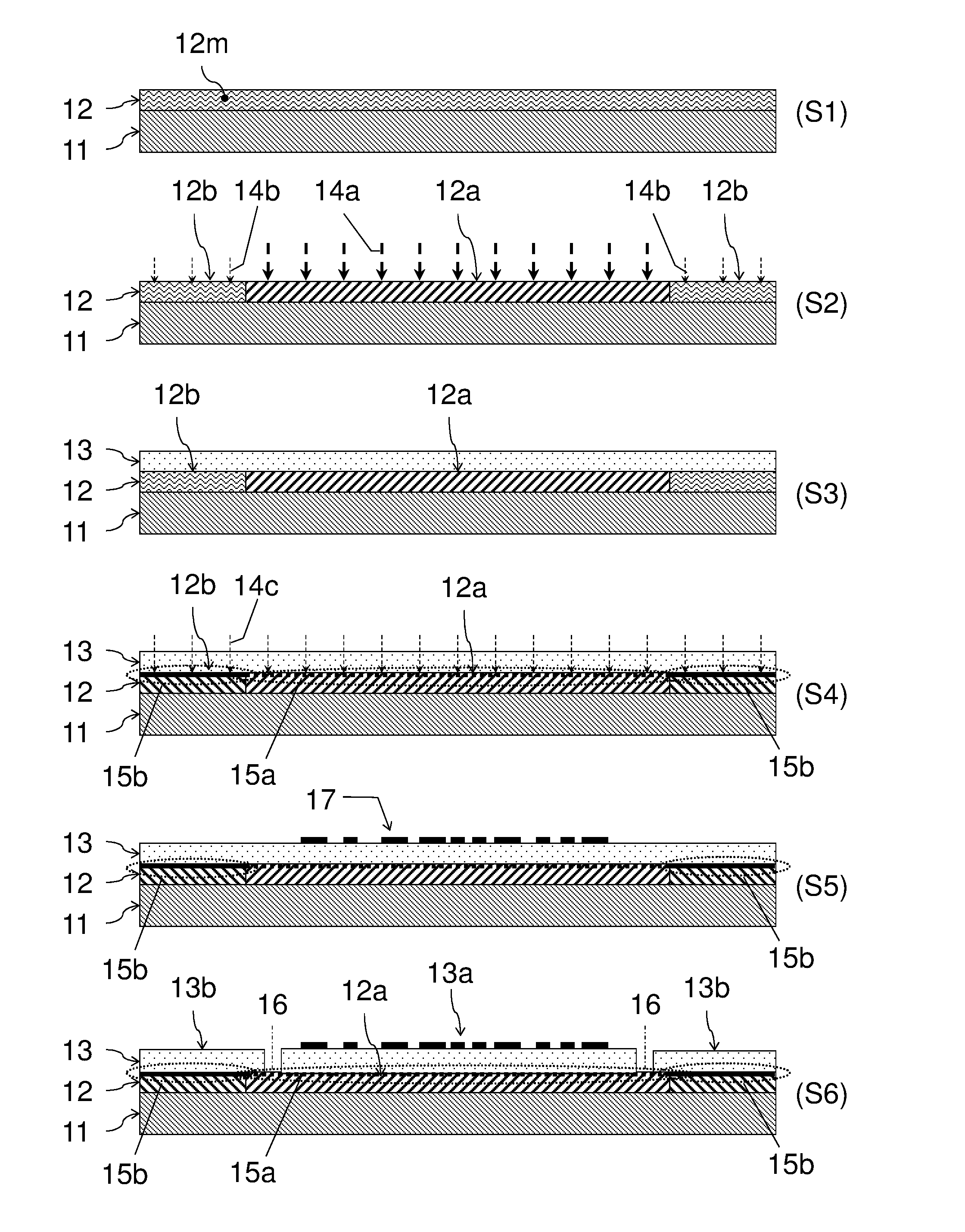
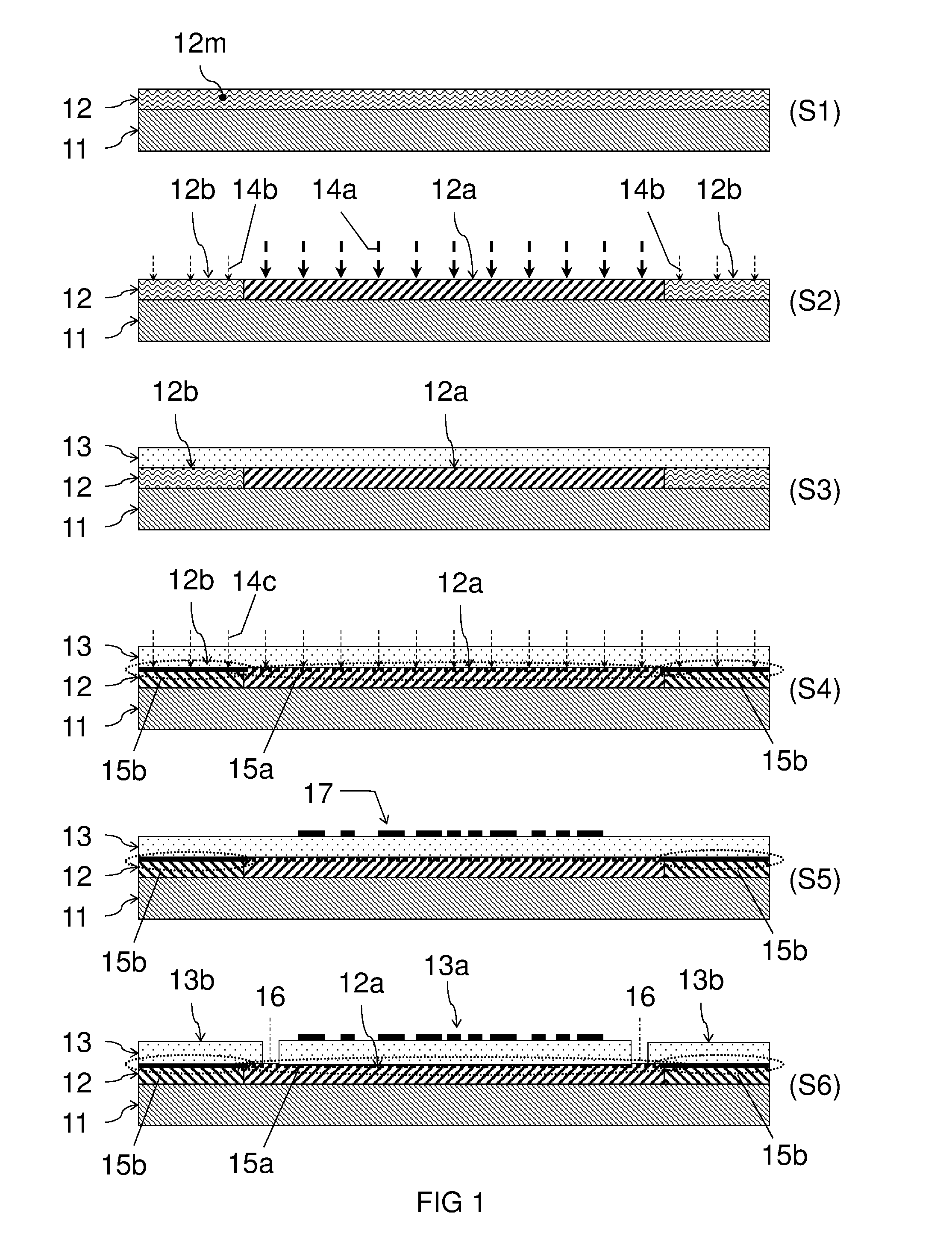
The patent describes a method for making a releasable substrate that can be easily removed after processing. The substrate is adhered to a carrier with a strong adhesion force and then cut along the perimeter inside a release area free of the adhesion force. This results in a substrate that can be released due to a relatively weak adhesion force at the release area. The method uses a bonding layer with a radiation curable adhesive that can be selectively controlled for different areas. The bonding layer can partially cure before contacting the substrate, resulting in a weaker or no connection therewith. This allows larger substrates to be processed without being damaged during processing or release. The releasable substrate on a carrier made by this method has similar advantages.

Problems solved by technology

Manufacturing of electronics, in particular integrated circuitry, may comprise harsh processing conditions, e.g. exposure to radiation and / or vacuum in a lithographic step, and / or exposure to high temperatures, e.g. during baking steps.
A problem encountered during manufacturing of electronics directly on a flexible substrate may be a low dimensional and / or thermal stability of the substrate.
This may result e.g. in alignment issues during lithographic exposure.
On the other hand the adhesion should not prevent release of the substrate from the carrier after manufacturing without damaging the electronics.
It can be challenge to find a compromise between these two criteria.
Unfortunately, such adhesive elements may not be suitable for withstanding high temperatures (>200° C.) or other harsh processing conditions encountered during manufacturing.
Unfortunately, this method relies on the foil being solution processed and able to adhere to the carrier.
Also, this method may be unsuitable for large substrates.

Method used


Image

  • Releasable substrate on a carrier
  • Releasable substrate on a carrier
  • Releasable substrate on a carrier

Examples


Embodiment Construction

[0028]Unless otherwise defined, all terms used herein have the same meaning as commonly understood by one of ordinary skill in the art to which this invention belongs as read in the context of the description and drawings. It will be further understood that terms, such as those defined in commonly used dictionaries, should be interpreted as having a meaning that is consistent with their meaning in the context of the relevant art and will not be interpreted in an idealized or overly formal sense unless expressly so defined herein. In some instances, detailed descriptions of well-known devices and methods may be omitted so as not to obscure the description of the present systems and methods. Terminology used for describing particular embodiments is not intended to be limiting of the invention. As used herein, the singular forms “a”, “an” and “the” are intended to include the plural forms as well, unless the context clearly indicates otherwise. The term “and / or” includes any and all co...


PUM


Abstract

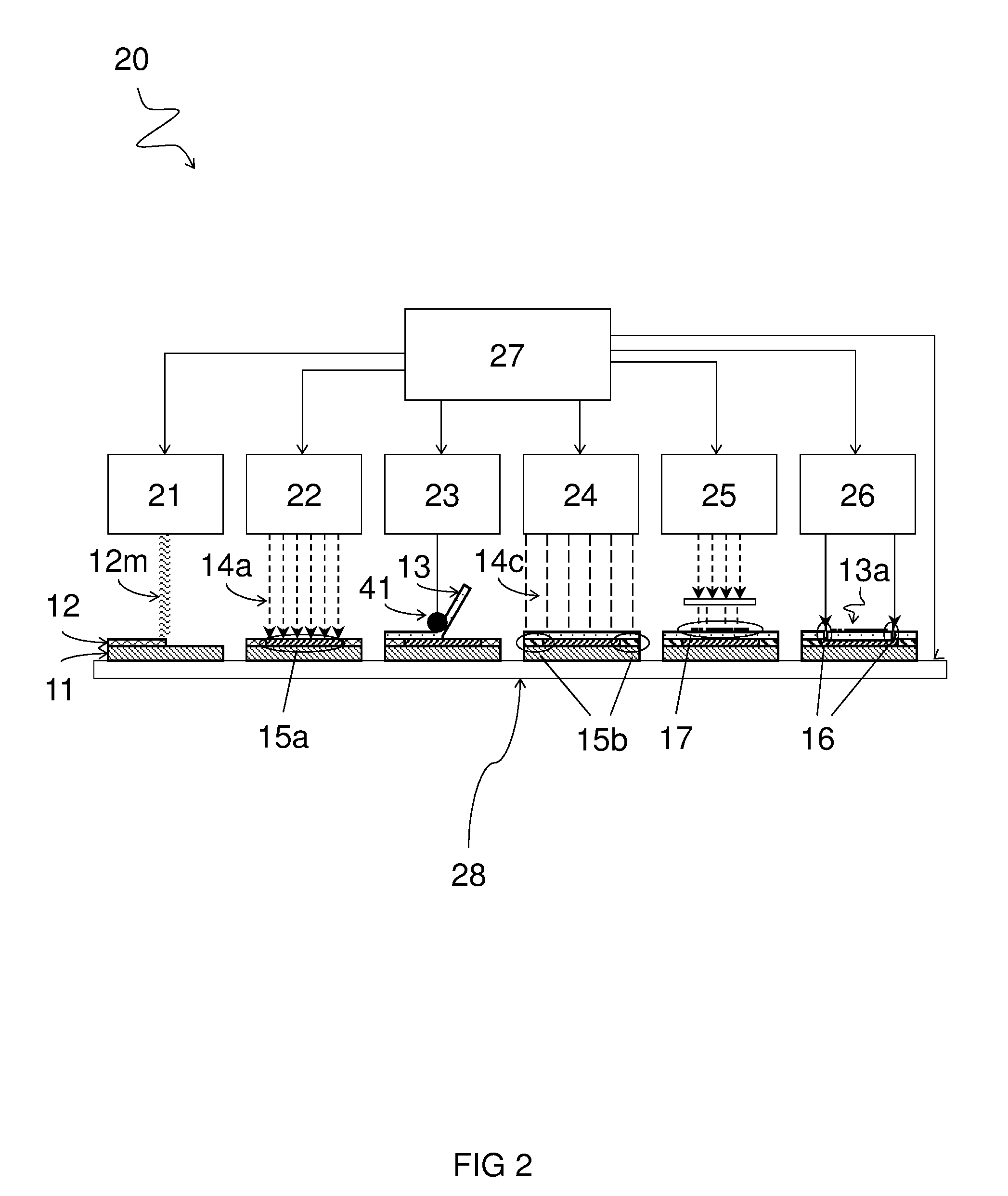
A method and system provide a releasable substrate on a carrier. The method includes providing the carrier with a bonding layer of radiation curable adhesive; selectively irradiating a first area subsection of the bonding layer with a first radiation for selectively at least partially curing the first area subsection; bringing a substrate in contact with the first area subsection and a second area subsection of the bonding layer; and curing the second area subsection in contact with the substrate for forming an adhesion area between the second area subsection and the substrate. The first area subsection forms a release area with an adhesion force between the bonding layer and the substrate lower in the release area than in the adhesion area as a result of the first area subsection being more cured than the second area subsection prior to being in contact with the substrate.

Description

FIELD AND BACKGROUND OF THE INVENTION[0001]The present invention relates to a releasable substrate on a carrier and a method and system for providing such. Flexible displays represent an upcoming trend in next-generation display technology. A flexible display may comprise a flexible substrate with electronics such as thin film transistors (TFT) or other components manufactured thereon. Manufacturing of electronics, in particular integrated circuitry, may comprise harsh processing conditions, e.g. exposure to radiation and / or vacuum in a lithographic step, and / or exposure to high temperatures, e.g. during baking steps. A problem encountered during manufacturing of electronics directly on a flexible substrate may be a low dimensional and / or thermal stability of the substrate. This may result e.g. in alignment issues during lithographic exposure. One solution for improving the stability of a substrate may be adhering the substrate to a carrier during manufacturing.[0002]On the one hand...

Claims


Application Information

Patent Timeline
IPC IPC(8): B32B7/12B32B7/14B32B37/12B32B38/00B32B37/00B32B39/00
CPCH01L21/6835H01L2221/68381H01L2221/68395H01L2221/6835H01L2221/68318Y10T428/24851Y10T156/1052B32B7/12B32B7/14B32B37/0046B32B37/12B32B38/0008B32B39/00B32B2037/1253B32B2307/546B32B2310/0831B32B2311/00B32B2457/00B32B2457/20
Inventor VAN NEER, MARTIN K.P.TEMPELAARS, KARINVAN LEUKEN, LINDA B.
Owner NEDERLANDSE ORG VOOR TOEGEPAST-NATUURWETENSCHAPPELIJK ONDERZOEK (TNO)
Learn More