Ophthalmologic apparatus

a technology of ophthalmologic equipment and eye examination, which is applied in the field of ophthalmologic equipment for eye examination, can solve the problems of difficult estimation of the axial length of the eye or the like in the conventional a-scan image obtained from one optical axis, inability to obtain correct values, etc., to achieve the effect of more accurate estimation

Active Publication Date: 2015-08-20
TOMEY CORP
View PDF1 Cites 5 Cited by
  • Summary
  • Abstract
  • Description
  • Claims
  • Application Information

AI Technical Summary

Benefits of technology

The ophthalmologic measuring apparatus described in this patent allows for the display of a three-dimensional image of the interior of the eye based on information collected from multiple optical axes. This allows for the visual inspection of the crystalline lens and retina, and the accurate estimation of values such as the axial length of the eye.

Problems solved by technology

However, since the A-scan image and the value such as the axial length of the eye, which are displayed on the monitor, are obtained from one optical axis, where a retina signal is weak, for example, due to opacity in the crystalline lens, or where there is a disease in the retina, the obtained value of the axial length of the eye or the like is difficult to estimate in the conventional A-scan image obtained from one optical axis, and the correct value sometimes cannot be obtained.
Furthermore, sometimes the value such as the axial length of the eye cannot be obtained due to the crystalline lens opacity or retina disease, or only values of low reliability and a large spread among the measurements are obtained.

Method used


Image

  • Ophthalmologic apparatus
  • Ophthalmologic apparatus
  • Ophthalmologic apparatus

Examples


embodiment

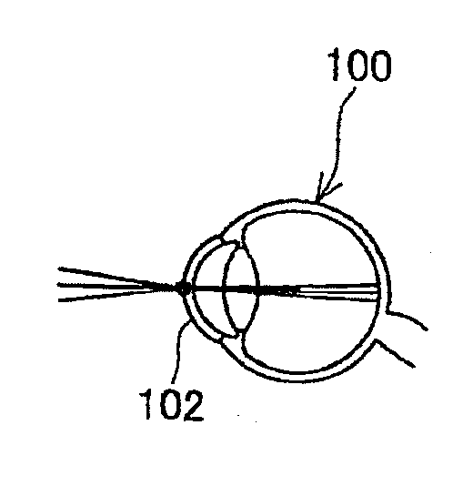
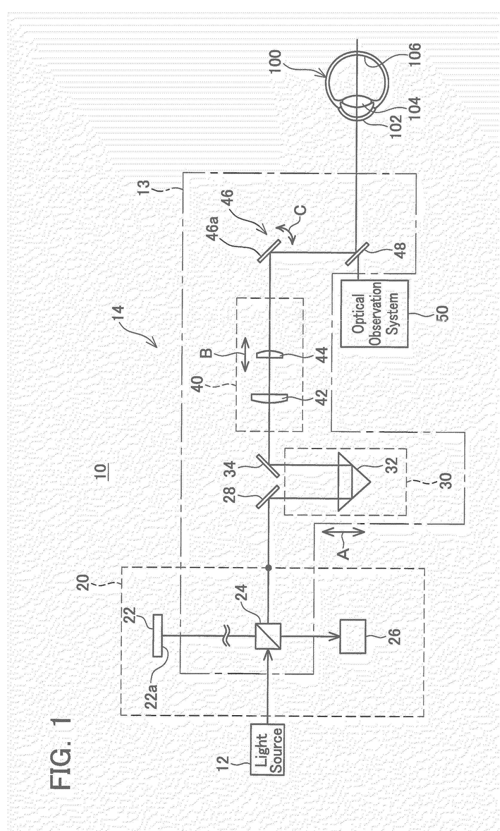
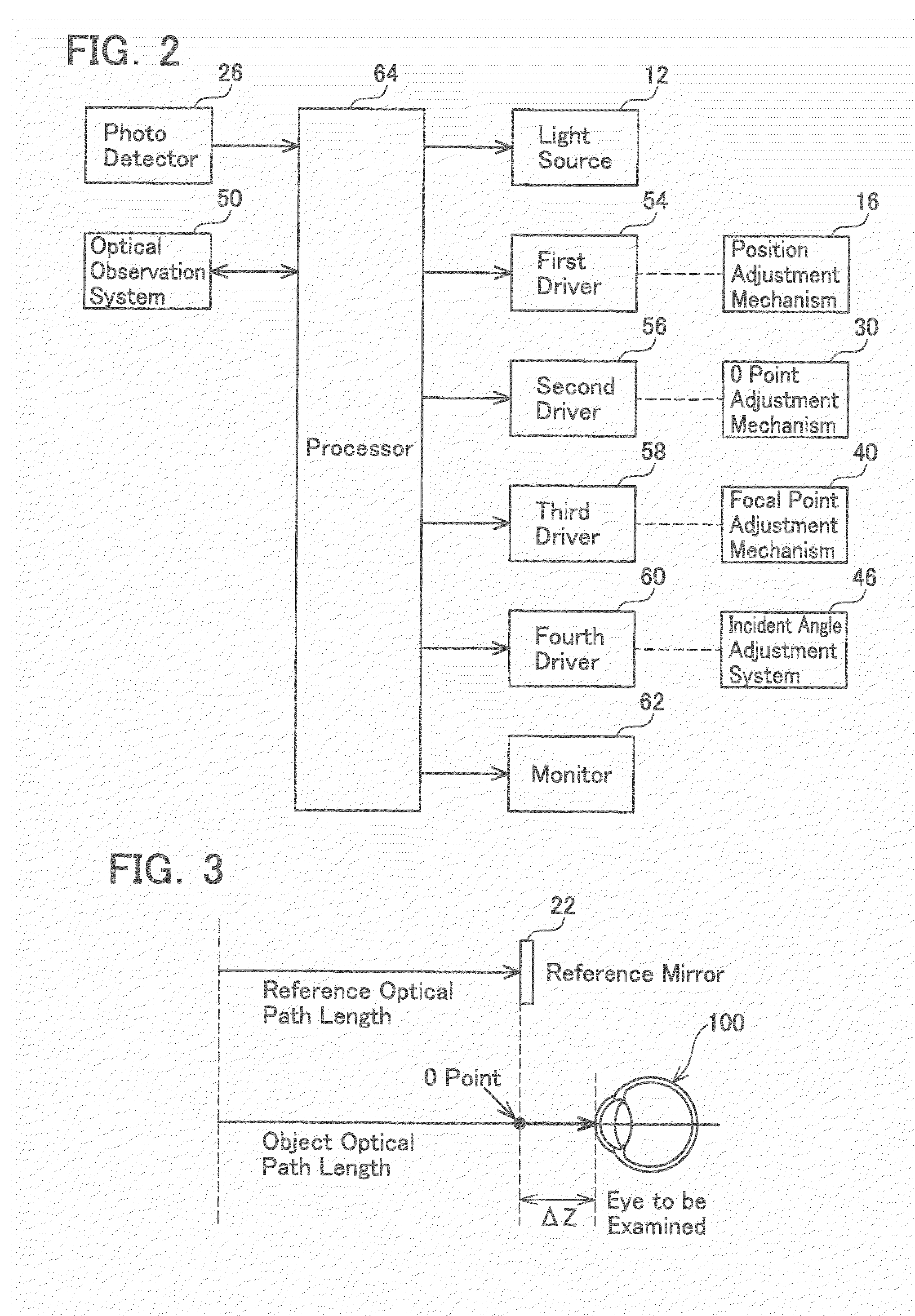
[0031](Embodiment) As shown in FIG. 1, an ophthalmologic apparatus of the present embodiment comprises a measurement unit 10 for examining an eye 100 to be examined. The measurement unit 10 comprises an optical interference system 14 that causes interference of a reflected light that is reflected from the eye 100 and a reference light, an optical observation system 50 that observes an anterior part of the eye 100, and an optical alignment system (not shown in the figure) for aligning the measurement unit 10 with respect to the eye 100 in a predetermined positional relationship. An optical alignment system that has been used in a well-known ophthalmologic apparatus can be used as the aforementioned optical alignment system, and detailed explanation thereof is herein omitted.

[0032]The optical interfering system 14 is configured by a light source 12, an optical measurement system 13 that radiates light from the light source 12 to inside the eye 100 and guides reflected light thereof, a...


PUM


Abstract

An ophthalmologic apparatus measures a dimension of an eye to be examined. The ophthalmologic apparatus includes a light source, an incidence member, an acquisition unit, and a display unit. The incidence member causes light from the light source to be incident on a plurality of different positions in the eye to be examined The acquisition unit acquires a two-dimensional tomographic image of an interior of the eye to be examined on the basis of a plurality of interference signals acquired as a result of the incidence member causing the incidence of light on the plurality of different positions. The display unit displays the acquired two-dimensional tomographic image.

Description

CROSS-REFERENCE TO RELATED APPLICATION[0001]This application claims priority to Japanese Patent Application No. 2014-030201 filed on Feb. 20, 2014, the contents of which are hereby incorporated by reference into the present application.TECHNICAL FIELD[0002]The present teachings relate to an ophthalmologic apparatus for eye examination, and more particularly to an ophthalmologic apparatus that determines a position of a measuring portion (for example, crystalline lens and retina) inside an eye.DESCRIPTION OF RELATED ART[0003]An ophthalmologic apparatus for examining an interior (for example, crystalline lens and retina) of an eye is being developed. The ophthalmologic apparatus of this type is provided with an optical measurement system that radiates light from a light source to inside the eye to be examined and guides the reflected light therefrom, and an optical reference system that radiates light from the light source to a reference surface and guides the reflected light therefro...

Claims


Application Information

Patent Timeline
IPC IPC(8): A61B3/14A61B3/00
CPCA61B3/0008A61B3/14A61B3/1005A61B3/102G01B9/02091G01B9/02004G01B9/02064G01B9/0203G01B9/02063G01B2290/65A61B3/0058A61B3/1025A61B3/117
Inventor KATO, CHIHIROOKOUCHI, KATSUMASA
Owner TOMEY CORP
Why Eureka
Try Eureka