Teleconverter lens and imaging apparatus

a technology of teleconverter lens and imaging apparatus, which is applied in the direction of optics, optical elements, instruments, etc., can solve the problems of disadvantages of using a plurality of lenses in view of both weight and cost, and achieve the effect of high image quality and sufficient optical performan

Active Publication Date: 2015-08-13
FUJIFILM CORP
View PDF3 Cites 1 Cited by
  • Summary
  • Abstract
  • Description
  • Claims
  • Application Information

AI Technical Summary

Benefits of technology

[0026]The teleconverter lens of the invention is a teleconverter lens attached to the object side of a master lens, the teleconverter lens consisting essentially of, in order from the object side: a front group having a positive refractive power; and a rear group having a negative refractive power, wherein the front group and the rear group are separated from each other by the widest air space, the front group consists essentially of one positive lens having a convex surface toward the object side, and the rear group comprises, in order f

Problems solved by technology

The teleconverter lenses taught in Patent Documents 1 to 4 have a configuration where the front group having a positive refractive power is formed by a plurality of lenses to the

Method used


Image

  • Teleconverter lens and imaging apparatus
  • Teleconverter lens and imaging apparatus
  • Teleconverter lens and imaging apparatus

Examples


Embodiment Construction

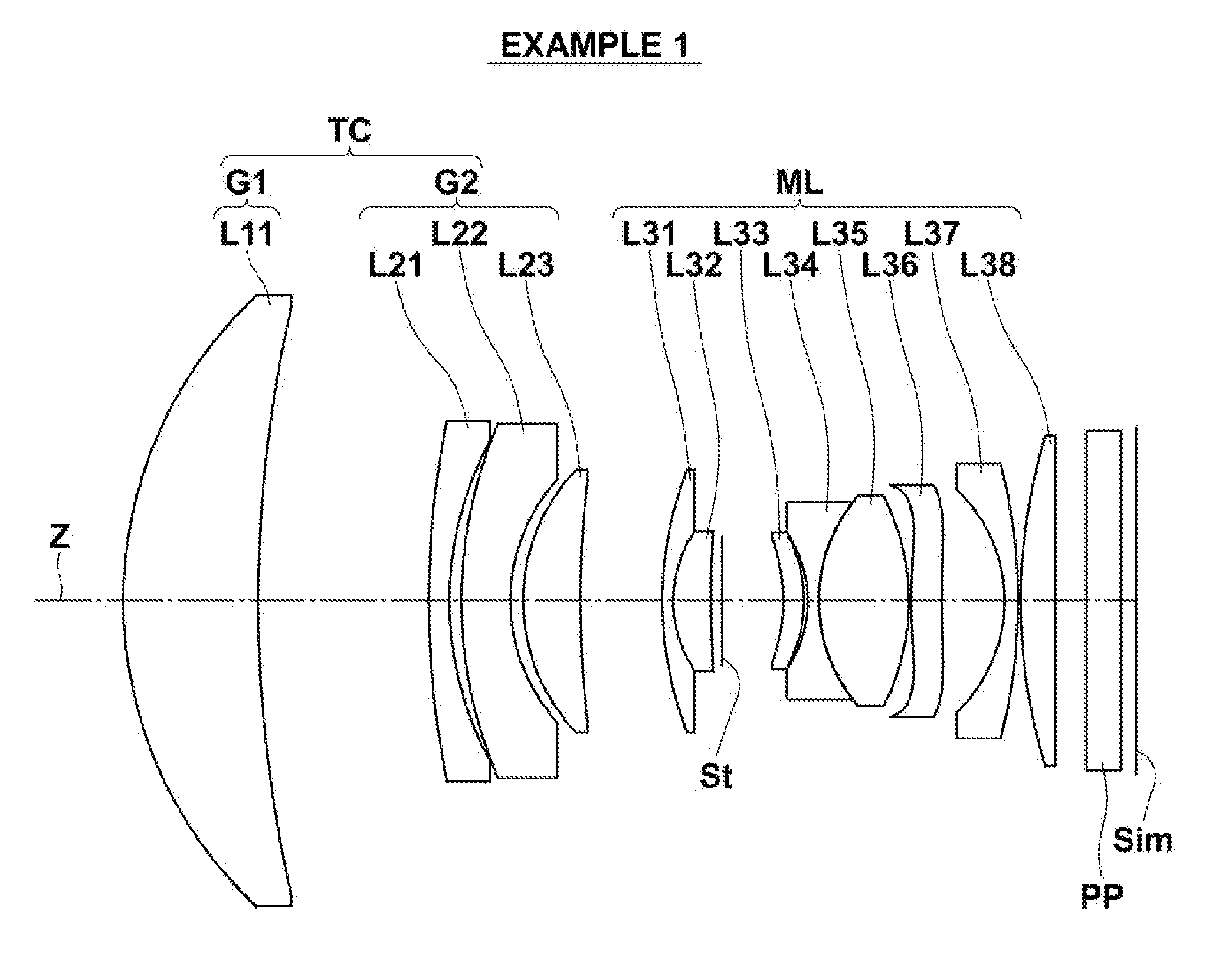
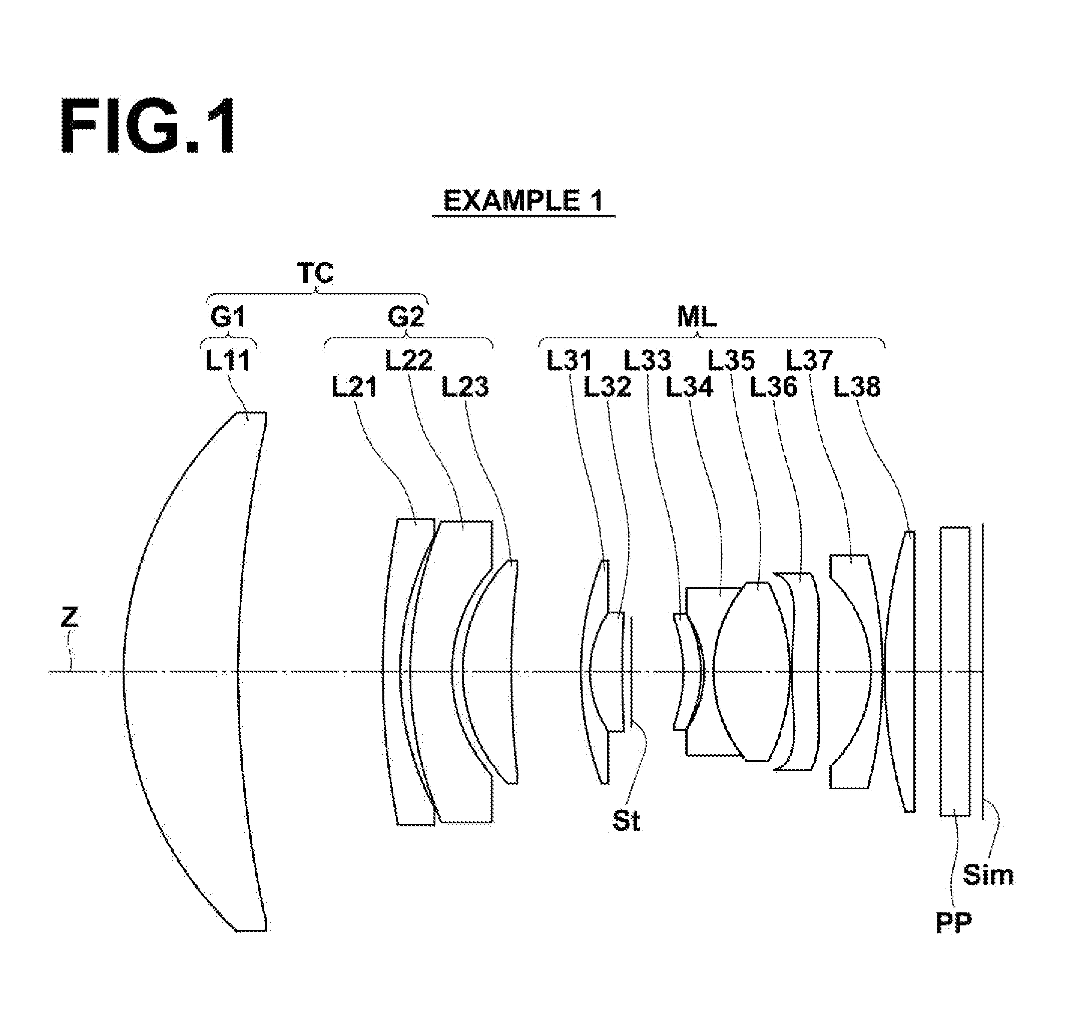
[0035]Hereinafter, embodiments of the present invention will be described in detail with reference to the drawings. FIG. 1 is a sectional view illustrating the lens configuration of a teleconverter lens according to one embodiment of the invention. The configuration example shown in FIG. 1 is the same as the configuration of a teleconverter lens of Example 1, which will be described later. In FIG. 1, the left side is the object side and the right side is the image side. FIG. 1 also shows an example of a master lens that is combined with the teleconverter lens of this embodiment.

[0036]As shown in FIG. 1, the teleconverter lens TC is attached to the object side of the master lens ML, and consists essentially of, in order from the object side along the optical axis Z, a front group G1 having a positive refractive power, and a rear group G2 having a negative refractive power, wherein the front group G1 and the rear group G2 are separated from each other by the widest air space, the fron...


PUM


Abstract

A teleconverter lens consists essentially of, in order from the object side: a front group having a positive refractive power; and a rear group having a negative refractive power, wherein the front group and the rear group are separated from each other by the widest air space, the front group consists essentially of one positive lens having a convex surface toward the object side, and the rear group includes, in order from the object side, at least one negative lens having a concave surface toward the image side, and at least one positive lens having a convex surface toward the object side.

Description

CROSS-REFERENCE TO RELATED APPLICATIONS[0001]The present application claims priority under 35 U.S.C. §119 to Japanese Patent Application No. 2014-021891, filed on Feb. 7, 2014. The above application is hereby expressly incorporated by reference, in its entirety, into the present application.BACKGROUND OF THE INVENTION[0002]1. Field of the Invention[0003]The present invention relates to a teleconverter lens that is attached, in particular, to the front side (object side) of an imaging lens (master lens) of an electronic camera, etc., to extend the focal length of the entire imaging lens, and an imaging apparatus provided with the teleconverter lens.[0004]2. Description of the Related Art[0005]As a so-called front teleconverter lens that is attached to the object side of an imaging lens to extend the focal length of the entire system, one configured such that the front group having a positive refractive power includes two positive lenses, as taught, for example, in Japanese Unexamined...

Claims


Application Information

Patent Timeline
IPC IPC(8): G02B15/12G02B9/38
CPCG02B9/38G02B15/12G02B15/00
Inventor SUZUKI, TAKASHI
Owner FUJIFILM CORP
Why Eureka
Try Eureka